
Ceramic raw material pug mill for domestic ceramic processing

A technology of ceramic processing and clay refining machine, which is applied in the field of ceramics, and can solve the problems of broken clay, easy adhesion on the inner wall of the machine, inconsistent particle gaps before and after the clay, etc.

Active Publication Date: 2021-04-27
应县宏达陶瓷股份有限公司
View PDF6 Cites 0 Cited by
  • Summary
  • Abstract
  • Description
  • Claims
  • Application Information

AI Technical Summary

Problems solved by technology

[0003] However, the clay is sticky and is easy to adhere to the inner wall of the machine, so that the pressure of the clay on the screw thread is too small. At the same time, the processed clay needs to be supplemented with subsequent clay during the extrusion process. When the pressure of the clay on the thread is too small The clay is not easy to enter into the thread, so that the processed clay has a broken flow phenomenon, so the gap between the front and rear particles of the processed clay is inconsistent, and the clay needs to be pressed manually

Method used


Image

  • Ceramic raw material pug mill for domestic ceramic processing
  • Ceramic raw material pug mill for domestic ceramic processing
  • Ceramic raw material pug mill for domestic ceramic processing

Examples


Embodiment 1

[0024] Such as Figure 1-Figure 5 Shown:

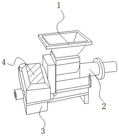
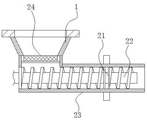
[0025] The present invention is a raw material mud refining machine for daily ceramic processing. Its structure includes a material inlet 1, a mud refining mechanism 2, a fixed platform 3, and a motor 4. The lower end of the motor 4 is welded on the left side of the upper end of the fixed platform 3. The mud refining mechanism 2 is installed on the right side of the upper end of the fixed platform 3. The mud refining mechanism 2 runs through the inside of the motor 4. The material inlet 1 is embedded in the upper end of the mud refining mechanism 2. The mud refining mechanism 2 is equipped with an extrusion Hole 21, rotating mechanism 22, mud practice cylinder 23, blocking mechanism 24, described extrusion hole 21 is snapped in the inside of mud practice cylinder 23, and the outer side of described rotation mechanism 22 is fit with the inner side of mud practice cylinder 23, and described blocking mechanism 24 is installed on the upp...

Embodiment 2

[0032] Such as Figure 6-Figure 7 Shown:

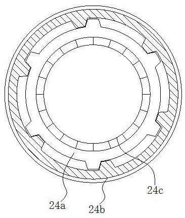
[0033] Wherein, the rotating mechanism 22 is provided with a rotating shaft w1, a supporting plate w2, a guiding mechanism w3, and a rotating thread w4. The rotating thread w4 is welded on the outside of the rotating shaft w1, and the supporting plate w2 is installed on the outside of the rotating thread w4. The guide mechanism w3 is embedded and fixed on the outside of the support plate w2, and the guide mechanism w3 is in clearance fit with the inner side of the mud training cylinder 23. There are six support plates w2, which are evenly distributed in a ring around the rotation axis w1, and each supports There are three guiding mechanisms w3 in the plate w2, so that the rotation of the motor 4 drives the rotating shaft w1 to rotate, so that the guiding mechanism w3 on the outside of the rotating thread w4 cooperates with the inner side of the clay training cylinder 23, so that the guiding mechanism w3 in the supporting plate w2 has ...


PUM


Abstract

The invention discloses a raw material pug mill for domestic ceramic processing, which structurally comprises a feeding port, a pugging mechanism, a fixing table and a motor. The lower end of the motor is welded to the left side of the upper end of the fixing table; the pugging mechanism is installed on the right side of the upper end of the fixing table; the pugging mechanism penetrates through the interior of the motor; and the feeding port is fixedly embedded in the upper end of the pugging mechanism. Through the effect that a guide plate extrudes a telescopic rod in a sponge block, the tightness of clay entering the guide plate under gravity is enhanced, the relatively tight clay moves downwards under the rotation of a threaded groove, and the clay is blocked through the lower end of a sliding ring, so that the clay is prevented from being extruded upwards during grinding; and a guide mechanism on the outer side of a rotary thread is in clearance fit with the inner side of a pugging barrel, the outer side of a bent plate is extruded by the inner side of the pugging barrel so as to be bent, and the clay moves towards the side face of the rotary thread in the guide plate, so that the rotary thread rotates to achieve the clay rolling effect, and the problem that the clay needs to be pressed manually to enter a rotary mechanism to be rolled is solved.

Description

technical field [0001] The invention relates to the field of ceramics, in particular to a raw material mud refining machine for daily ceramic processing. Background technique [0002] In the production and processing of ceramics, it is necessary to carry out mud refining treatment on the ceramic clay through the mud refining machine, so as to ensure the high quality of the ceramic clay. Make the clay move in one direction, remove the air in the clay through active extrusion, and rearrange the gaps between the soil particles in the clay. [0003] However, the clay is sticky and is easy to adhere to the inner wall of the machine, so that the pressure of the clay on the screw thread is too small. At the same time, the processed clay needs to be supplemented with subsequent clay during the extrusion process. When the pressure of the clay on the thread is too small The clay is not easy to enter the thread, so that the processed clay has a phenomenon of cut-off, so the gaps betwe...

Claims


Application Information

Patent Timeline
Patent Type & Authority Applications(China)
IPC IPC(8): B28C1/16
CPCB28C1/16Y02P40/60
Inventor 王玉秀
Owner 应县宏达陶瓷股份有限公司
Learn More