A pin transfer transport device

A transport device and pin shaft technology, applied in the field of pin shaft transfer transport devices, can solve the problems of unfavorable economy and flexibility of forklifts, scratches on the paint surface, and unfavorable selection and use by users, and achieve convenient storage, convenient storage and The effect of taking out, strong practicality

Active Publication Date: 2022-06-03
山东华伟重特机械有限公司
View PDF4 Cites 0 Cited by
  • Summary
  • Abstract
  • Description
  • Claims
  • Application Information

AI Technical Summary

Problems solved by technology

[0003] Traditional pins are often placed in a box during transfer and transportation, which is likely to cause bumps and scratches on the paint surface. It is also not conducive to the selection and use of users when they are delivered to users. At the same time, it is not conducive to the economy to use forklifts when there are too many deliveries. and flexibility, so we propose a pin transfer transport device to solve the above-mentioned problems

Method used


Image

  • A pin transfer transport device
  • A pin transfer transport device
  • A pin transfer transport device

Examples


Embodiment 1

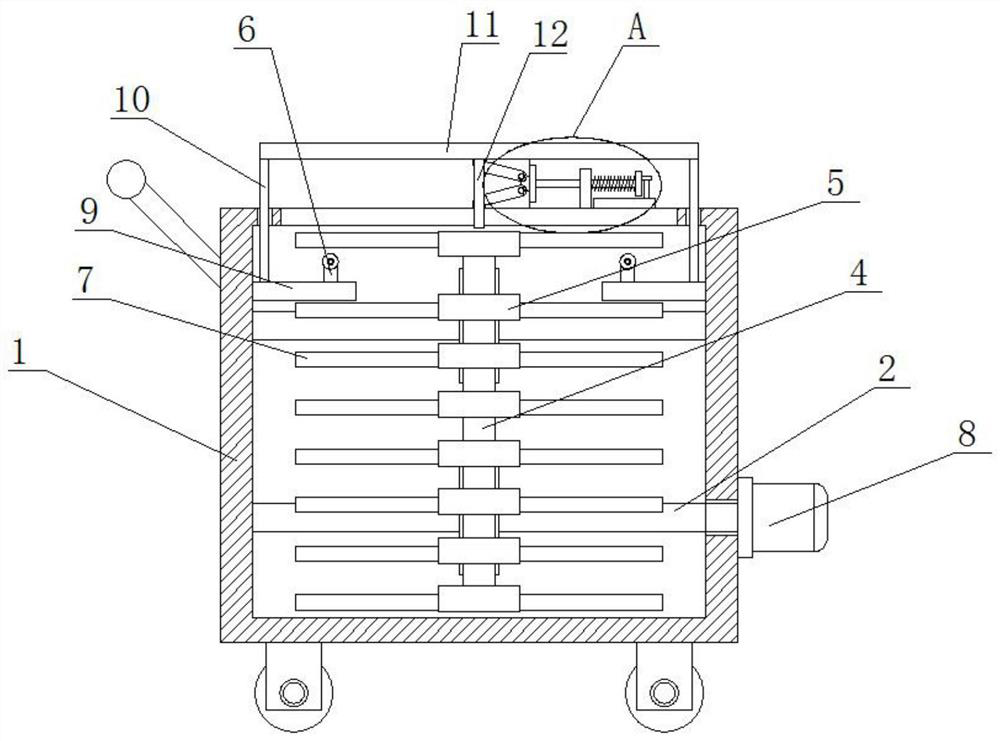
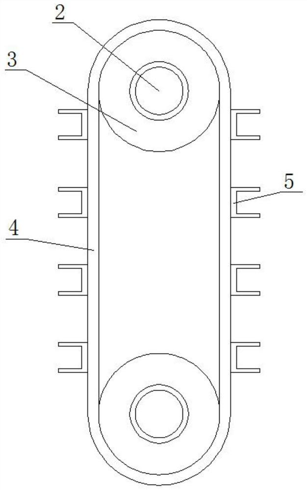
[0025] refer to Figure 1-5 , In this embodiment, a pin shaft transfer and transportation device is proposed, including a transportation box 1. Wheels are rotatably connected to the bottom four corners of the transportation box 1, and a handle is fixedly installed on the top of one side of the transportation box 1. The transportation box 1 There are two rotating shafts 2 symmetrically connected to the inner wall of the transport box 2, and a turntable 3 is fixedly installed on the two rotating shafts 2. The two turntables 3 are connected with the same transmission belt 4 for transmission. The bottom of the other side of the transport box 1 is fixedly installed with a drive The motor 8, and the driving motor 8 is fixedly connected with one end of the rotating shaft 2 located below, and a plurality of U-shaped plates 5 are fixedly installed on the transmission belt 4 at equal intervals. The pin shaft 7 is installed, the top inner wall of the transport box 1 is provided with a ta...

Embodiment 2

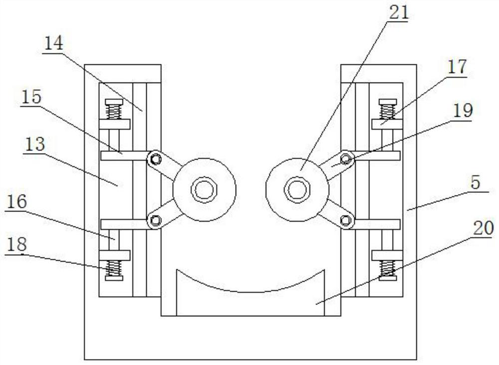
[0028] In this embodiment, the clamping assembly includes connecting grooves 13 formed on the inner walls of both sides of the U-shaped plate 5 , and two sliding plates 15 are symmetrically slidably connected in the connecting groove 13 , and one side of the two sliding plates 15 is connected by rotation. There is a connecting rod 19, and one end of the two connecting rods 19 extends to the outside of the connecting groove 13 and is rotatably connected with the same limit wheel 21, the limit plate 20 is fixedly installed on the inner wall of the U-shaped plate 5, and the two limit Both the position wheel 21 and the limit plate 20 are clamped with the pin shaft 7 , and the pin shaft 7 can be easily clamped by using the two limit wheels 21 and the limit plate 21 .

[0029] In this embodiment, the sliding rod 14 is fixedly installed on the inner wall of the connecting groove 13 , and the two sliding plates 15 are both slidably sleeved on the sliding rod 14 , and two fixed plates a...


PUM


Abstract

The invention belongs to the field of transportation devices, in particular to a pin shaft transfer transportation device, aiming at the problem of bumps and scratches during the transportation of various types of pin shafts in the process of transportation, as well as the fact that there is no confusion in the distribution of complete sets during use, which is not conducive to selection Problem, the following proposal is now proposed, which includes a transport box, wheels are rotatably connected to the four corners of the bottom of the transport box, and a handle is fixedly installed on the top of one side of the transport box, and the inner wall of the transport box is symmetrically rotatably connected to There are two rotating shafts, and the turntables are fixedly installed on the two rotating shafts. By setting a plurality of U-shaped plates in the present invention, it is convenient to store and limit the positions of multiple pin shafts, and there will be no contact between the multiple pin shafts. , so there will be no friction, and it is convenient to take out the pin shaft from the transport box, so it will be more convenient to take the pin shaft. Strong practicality.

Description

technical field [0001] The invention relates to the technical field of transport devices, in particular to a pin shaft transfer transport device. Background technique [0002] The pin shaft is a kind of standardized fastener, which can be fixed statically or moved relative to the connected parts. It is mainly used for the hinged connection of two parts to form a hinged connection. The pin is usually locked with a split pin, which is reliable and easy to disassemble. [0003] Traditional pins are often put into a box during the transfer and transportation process, which is easy to cause bumps and scratches on the paint surface. It is not conducive to the selection and use of users when they are distributed to users. At the same time, it is not economical to use a forklift for more distribution. and flexibility, so we propose a pin-shaft transfer transportation device to solve the above-mentioned problems. SUMMARY OF THE INVENTION [0004] Based on the technical problems o...

Claims


Application Information

Patent Timeline
Patent Type & Authority Patents(China)
IPC IPC(8): B62B3/04B62B3/02
CPCB62B3/04B62B3/02B62B2205/006
Inventor 张霞高祥蒙
Owner 山东华伟重特机械有限公司
Why Eureka
Try Eureka