Novel aerospace craft and flight propulsion method thereof

A space vehicle and a new type of technology, applied in the aerospace field, can solve the problems of small load, high rocket cost, high launch cost, etc., and achieve the effect of reducing the carrying cost and overcoming the high cost

Pending Publication Date: 2021-04-27
王国忠
View PDF0 Cites 0 Cited by
  • Summary
  • Abstract
  • Description
  • Claims
  • Application Information

AI Technical Summary

Problems solved by technology

[0003] The advantage of the rocket is that it can fly at high speed in the interstellar space without air, but the disadvantage of the rocket is also very obvious, that is, the total thrust of the engine of the first stage of the rocket must exceed the weight of the rocket itself to take off
At the same time, most of the rocket itself is fuel, and the weight of the load is extremely small; the cost of launching the rocket is extremely high
In addition, compared with airplanes, the fuel thermal efficiency and load factor of rockets are very low, and the launch cost is high

Method used


Image

  • Novel aerospace craft and flight propulsion method thereof

Examples


Embodiment 1

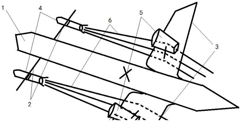
[0027] A novel aerospace vehicle comprises a fuselage 1, a first wing 2, a second wing 3, a rocket engine 4 and a turbofan engine 5.

[0028] The fuselage 1 is similar to the fuselage structure of a fixed-wing aircraft. The fuselage 1 includes a fuselage head, a fuselage middle and a fuselage tail arranged in sequence.

[0029] The first wing 2 and the second wing 3 are all arranged in pairs; wherein, the first wing 2 is symmetrically fixedly connected on both sides of the fuselage head; the second wing 3 is symmetrically arranged on both sides of the fuselage middle, and the second The wing 3 can rotate and change shape relative to the fuselage 1 to adjust the lift and drag generated by the second wing 3 under the impact of the high-temperature and high-pressure exhaust gas flow 6 generated by the rocket engine 4 .

[0030] In this embodiment, both the first wing 2 and the second wing 3 are a pair.

[0031] The first wing 2 is provided with a rocket engine 4, and the second ...

Embodiment 2

[0038] A kind of flight propulsion method of novel aerospace vehicle, uses the novel aerospace vehicle of embodiment 1, and its method comprises the following steps:

[0039] S10, when flying in the atmosphere, the novel aerospace vehicle is provided with thrust by the turbofan engine 5, and the second wing 3 provides lift;

[0040] S20, when flying in a space with thin air, the turbofan engine 5 is turned off, and the rocket engine 4 works;

[0041] S30, drive the second wing 3 to rotate through the first driving device, the second wing 3 rotates and changes shape relative to the fuselage 1, so as to adjust the impact of the second wing 3 on the high-temperature and high-pressure exhaust gas flow 6 generated by the rocket engine The lift and drag generated by the

[0042] S40, when flying in an airless space, all are powered by the rocket engine 4 .

[0043] In this embodiment, the take-off mode and recovery landing mode of the new aerospace vehicle are similar to those of ...


PUM


Abstract

The invention discloses a novel aerospace craft, which belongs to the technical field of aerospace; and the novel aerospace craft comprises a fuselage, first wings, second wings, a rocket engine and a turbofan engine; the fuselage comprises a fuselage head, a fuselage middle part and a fuselage tail part which are sequentially arranged from front to back; the first wings and the second wings are arranged in pairs; the first wings are symmetrically and fixedly connected to two sides of the head of the fuselage; the second wings are symmetrically arranged on the two sides of the middle of the fuselage and can rotate relative to the fuselage and change the shape, and lift force and resistance generated by the second wings under impact of high-temperature and high-pressure tail gas flow generated by the rocket engine are adjusted. Rocket engines are arranged on the first wings, and turbofan engines are arranged on the second wings or the tail of the fuselage. The defects that a rocket is high in cost and extremely low in carrying coefficient are overcome, the rocket can be repeatedly used like an airplane while entering the space, and the flight carrying cost of a spacecraft is greatly reduced.

Description

technical field [0001] The invention belongs to the field of aerospace technology, and in particular relates to a novel aerospace vehicle and a flight propulsion method thereof. Background technique [0002] Rockets are another type of aircraft that work differently than airplanes, and are currently the only vehicle for launching satellites and planetary probes. The rocket has its own oxidant and fuel, and the rocket engine uses the fuel and oxidant to burn violently in the combustion chamber to generate high-temperature and high-pressure gas to obtain thrust. [0003] The advantage of the rocket is that it can fly at high speed in the airless interstellar space, but the disadvantage of the rocket is also very obvious, that is, the total thrust of the engine of the first stage of the rocket must exceed the weight of the rocket itself to take off. At the same time, most of the rocket itself is fuel, and the weight of the load is extremely small; the cost of launching the roc...

Claims


Application Information

Patent Timeline
IPC IPC(8): B64G1/40
CPCB64G1/40
Inventor 王国忠
Owner 王国忠
Why Eureka
Try Eureka