
Spherical lander and planet landing method using spherical lander

A lander, spherical technology, applied in the direction of space vehicle landing device, system of space vehicle return to the earth's atmosphere, etc., can solve the problems of fuel consumption, lander stability, poor safety, easy to fall, etc., to improve stability performance and the effect of reducing fuel consumption

Active Publication Date: 2021-04-27
HARBIN INST OF TECH
View PDF5 Cites 0 Cited by
  • Summary
  • Abstract
  • Description
  • Claims
  • Application Information

AI Technical Summary

Problems solved by technology

[0004] The purpose of the present invention is to propose a spherical lander and a planetary landing method using a spherical lander in order to solve the problems of the existing lander in the landing process, such as poor stability, poor safety, easy toppling over, and consumption of a large amount of fuel

Method used


Image

  • Spherical lander and planet landing method using spherical lander
  • Spherical lander and planet landing method using spherical lander
  • Spherical lander and planet landing method using spherical lander

Examples


specific Embodiment approach 1

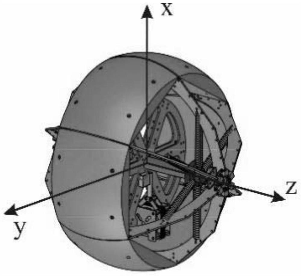
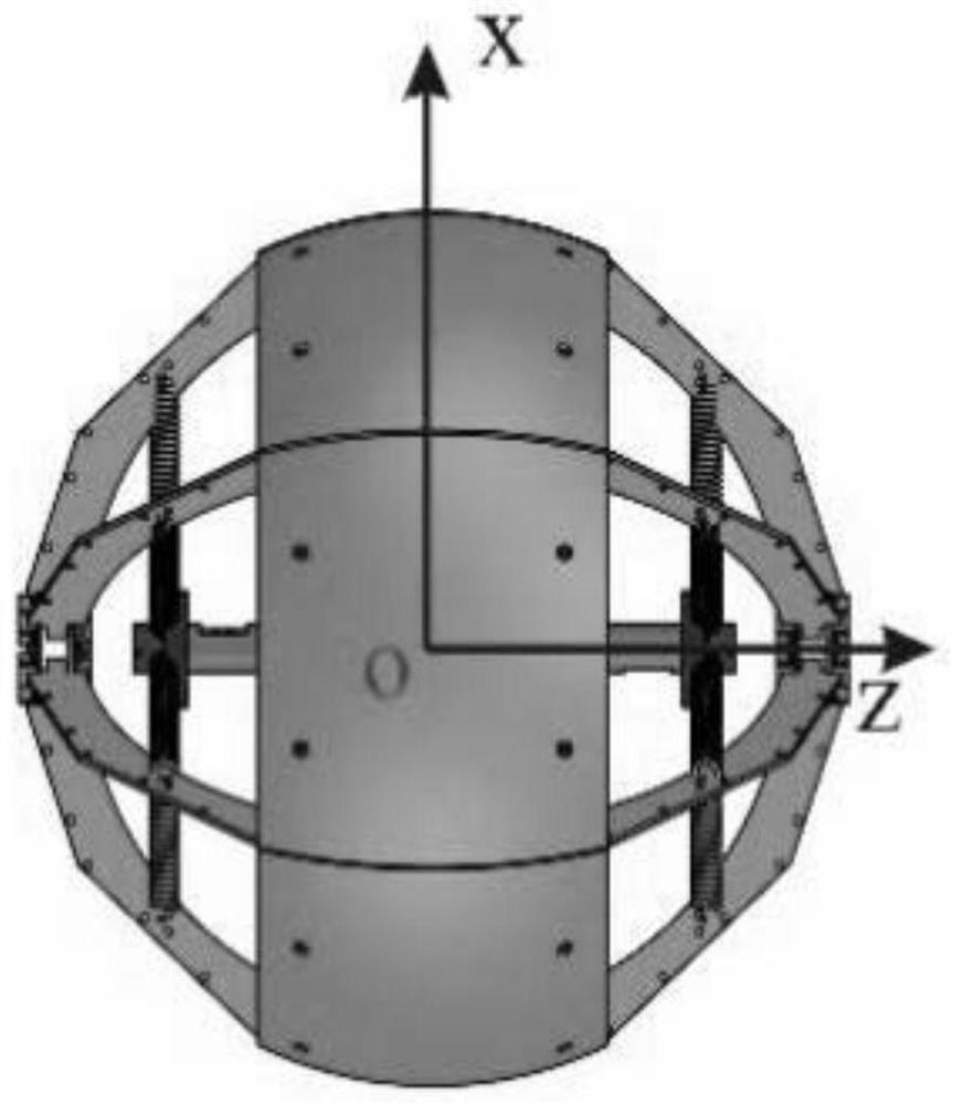
[0042] Specific Embodiment 1: A spherical lander in this embodiment includes: the spherical lander includes a spherical shell and an eccentric plate;

[0043] The spherical shell is composed of six frame rods and a cover plate, and the cover plate covers the six frame rods and wraps the six frame rods;

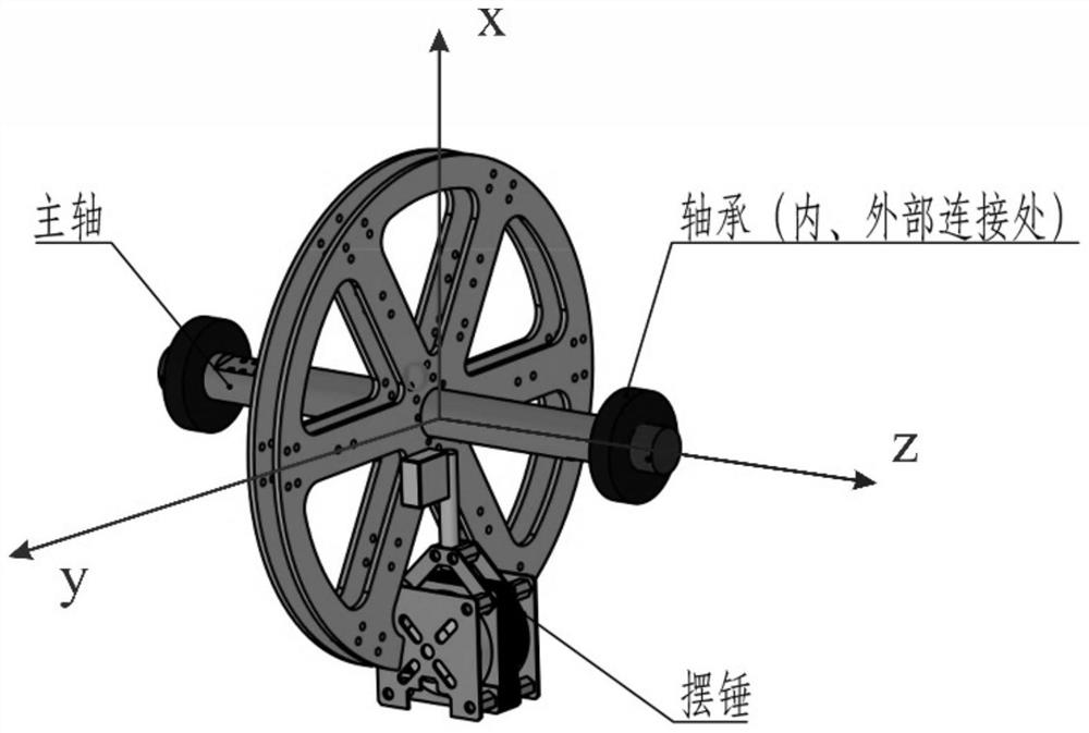
[0044] The eccentric disc includes disc, bearing, main shaft and pendulum; the eccentric disc structure (such as figure 1 , image 3 );

[0045] The disk is divided into six hollow areas according to the central angle, the central angle of each hollow area is 60 degrees, and one of the hollow areas lacks the bottom edge of the arc;

[0046] The main shaft runs through the center of the disc and is set perpendicular to the disc surface;

[0047] The bearing sleeves are located at both ends of the main shaft and are set concentrically with the main shaft;

[0048] The pendulum is installed at the center of the eccentric disc;

[0049] The center of gravity of the eccentric ...

specific Embodiment approach 2

[0052] Embodiment 2: This embodiment differs from Embodiment 1 in that the eccentric plate is connected to the spherical shell through a separation mechanism, so that the direction of the pendulum is consistent with the direction of the thruster or paraglider.

[0053] Before the separation mechanism is unlocked, the eccentric plate is fixedly connected with the spherical shell; after the separation mechanism is unlocked, the eccentric plate is rotatably connected with the spherical shell, and the spherical shell can freely rotate around the main axis (z axis) relative to the eccentric plate.

[0054] Other steps and parameters are the same as those in Embodiment 1.

specific Embodiment approach 3

[0055] Embodiment 3: The difference between this embodiment and Embodiment 1 or 2 is that the separation mechanism is installed at the shortest distance between the six support rods and the eccentric plate.

[0056] Other steps and parameters are the same as those in Embodiment 1 or Embodiment 2.


PUM


Abstract

The invention discloses a spherical lander and a planet landing method using the spherical lander, and relates to the spherical lander and the planet landing method using the spherical lander. The invention aims at solving the problems that an existing lander is poor in stability and safety in the landing process, prone to turnover and capable of consuming a large amount of fuel. The process is as follows: the spherical lander comprises a spherical shell and an eccentric weight disc; the spherical shell is composed of six frame rods and a cover plate, and the cover plate covers the six frame rods and wraps the six frame rods. The eccentric weight disc comprises a disc, bearings, a main shaft and a pendulum bob to form a control system to stabilize the sphere posture; the main shaft penetrates through the center of the disc and is perpendicular to the surface of the disc; the bearings sleeve the two ends of the main shaft and are coaxially arranged with the main shaft; the pendulum bob is arranged at the circle center of the eccentric weight disc; the center of gravity of the eccentric weight disc is located below the center. Landing is carried out in a slow descending and rolling mode after touching the ground. The invention is used in the field of landers.

Description

technical field [0001] The invention relates to a spherical lander and a planetary landing method using the spherical lander. Background technique [0002] With the rapid development of deep space exploration, more and more planetary landers have been launched to the surface of the planet. In the exploration mission, the landing technology is one of the key technologies developed, and it is very important to improve the reliability of the landing process. Existing landers are divided into fixed landers (such as Chang'e-4) and mobile landers (such as Mars rovers), and landing buffer technologies are divided into airbags and shock absorbing rods. Soft landing is the main landing method at this stage. It completely eliminates the ground speed during the landing process and consumes a lot of fuel. Therefore, improving the stability and safety of the landing process, avoiding overturning and carrying more payload is the main direction of future development, which puts forward n...

Claims


Application Information

Patent Timeline
IPC IPC(8): B64G1/62
CPCB64G1/62
Inventor 叶东王纪元程诺曲胜峰许家凯孙宇
Owner HARBIN INST OF TECH
Learn More