Dry-connected fabricated reinforced concrete column unit
A technology for reinforced concrete columns and concrete-filled steel tubes, which is applied to columns, pillars, piers and other directions, can solve the problems of difficult quality inspection and low installation efficiency, and achieve the effect of shortening the construction period, improving the bearing capacity of the structure, and reducing the difficulty of inspection.
- Summary
- Abstract
- Description
- Claims
- Application Information
AI Technical Summary
Problems solved by technology
Method used
Image

Examples
specific Embodiment approach 1
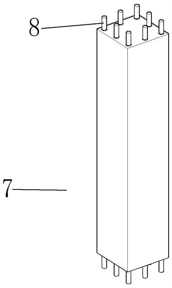
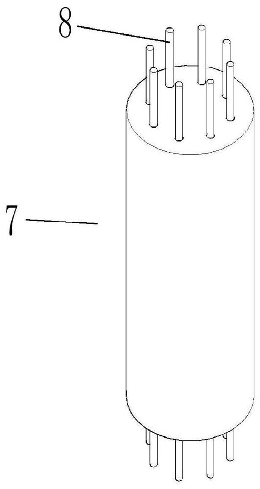
[0040] A prefabricated reinforced concrete column unit with dry connection, the outstretched longitudinal bars 8 at the upper and lower ends of the prefabricated reinforced concrete column unit 7 can be connected to the connecting device 1 through the mounting hole 5 of the column connecting plate 3 (such as figure 1 , 2 ), the connecting device 1 at the upper and lower ends of the prefabricated reinforced concrete column unit 7 can be connected to the vertical longitudinal bars 10 of the upper and lower nodes 9 through the installation holes 5 of the node connecting plate 2 (such as Figure 3-6 ), so that the prefabricated reinforced concrete column unit 7 and the node 9 are integrated vertically through a dry connection (such as Figure 7 , 8 ).
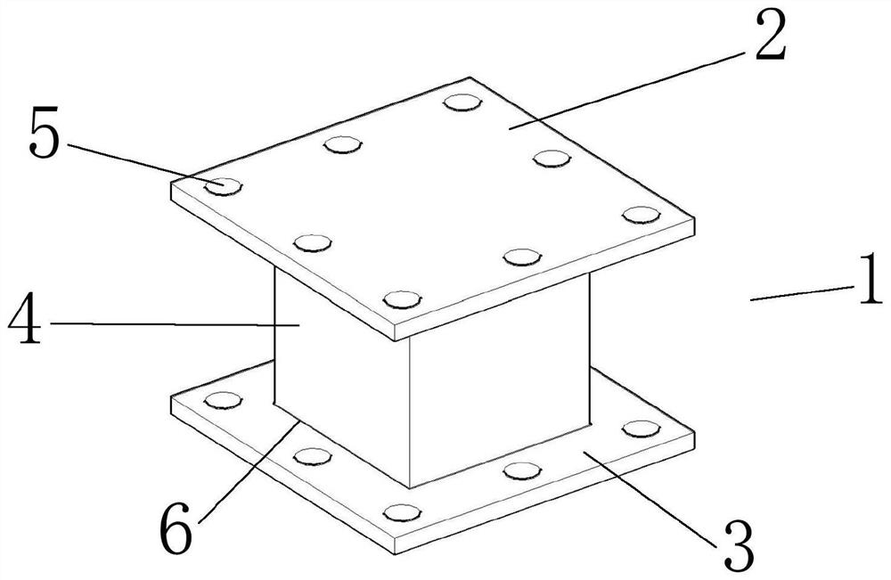
[0041] Further, the connection device 1 includes a node connecting plate 2, a column connecting plate 3 and a short concrete-filled steel tube column 4. The node connecting plate 2 is provided with an installation hole 5 through ...
specific Embodiment approach 2
[0046] A prefabricated reinforced concrete column unit with dry connection, the outstretched longitudinal bars 8 at the upper and lower ends of the prefabricated reinforced concrete column unit 7 can be connected to the connecting device 1 through the mounting hole 5 of the column connecting plate 3 (such as figure 1 , 2 ), the connecting device 1 at the upper and lower ends of the prefabricated reinforced concrete column unit 7 can be connected to the vertical longitudinal bars 10 of the upper and lower nodes 9 through the installation holes 5 of the node connecting plate 2 (such as Figure 3-6 ), so that the prefabricated reinforced concrete column unit 7 and the node 9 are integrated vertically through a dry connection (such as Figure 7 , 8 ).
[0047]Further, the short concrete-filled steel tube column 4 is geometrically centered by one end of the empty steel tube and the node connecting plate 2 or the column connecting plate 3 and connected by the weld 6, and then conc...
specific Embodiment approach 3
[0050] A prefabricated reinforced concrete column unit with dry connection, the outstretched longitudinal bars 8 at the upper and lower ends of the prefabricated reinforced concrete column unit 7 can be connected to the connecting device 1 through the mounting hole 5 of the column connecting plate 3 (such as figure 1 , 2 ), the connecting device 1 at the upper and lower ends of the prefabricated reinforced concrete column unit 7 can be connected to the vertical longitudinal bars 10 of the upper and lower nodes 9 through the installation holes 5 of the node connecting plate 2 (such as Figure 3-6 ), so that the prefabricated reinforced concrete column unit 7 and the node 9 are integrated vertically through a dry connection (such as Figure 7 , 8 ).
[0051] Further, the node connecting plate 2 and the column connecting plate 3 are rectangular, circular, or shaped.
[0052] Further, the cross-section of the short concrete-filled steel tube column 4 is rectangular, circular, o...
PUM
 Abstract
Description
Claims
Application Information
 - Generate Ideas
- Intellectual Property
- Life Sciences
- Materials
- Tech Scout
- Unparalleled Data Quality
- Higher Quality Content
- 60% Fewer Hallucinations
Browse by: Latest US Patents, China's latest patents, Technical Efficacy Thesaurus, Application Domain, Technology Topic, Popular Technical Reports.
© 2025 PatSnap. All rights reserved.Legal|Privacy policy|Modern Slavery Act Transparency Statement|Sitemap|About US| Contact US: help@patsnap.com