

Differential device
A technology for differentials and differential cases, applied in the direction of differential transmissions, transmissions, mechanical equipment, etc., which can solve problems that are difficult to eliminate, wear and tear, and impede durability improvement
- Summary
- Abstract
- Description
- Claims
- Application Information
AI Technical Summary
Problems solved by technology
Method used
Image

Examples
no. 1 approach >
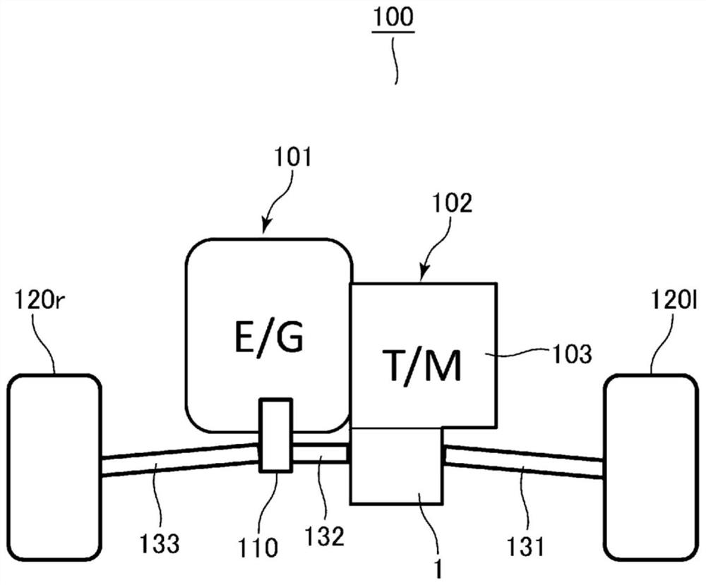
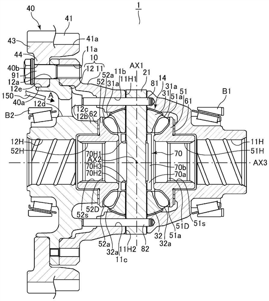
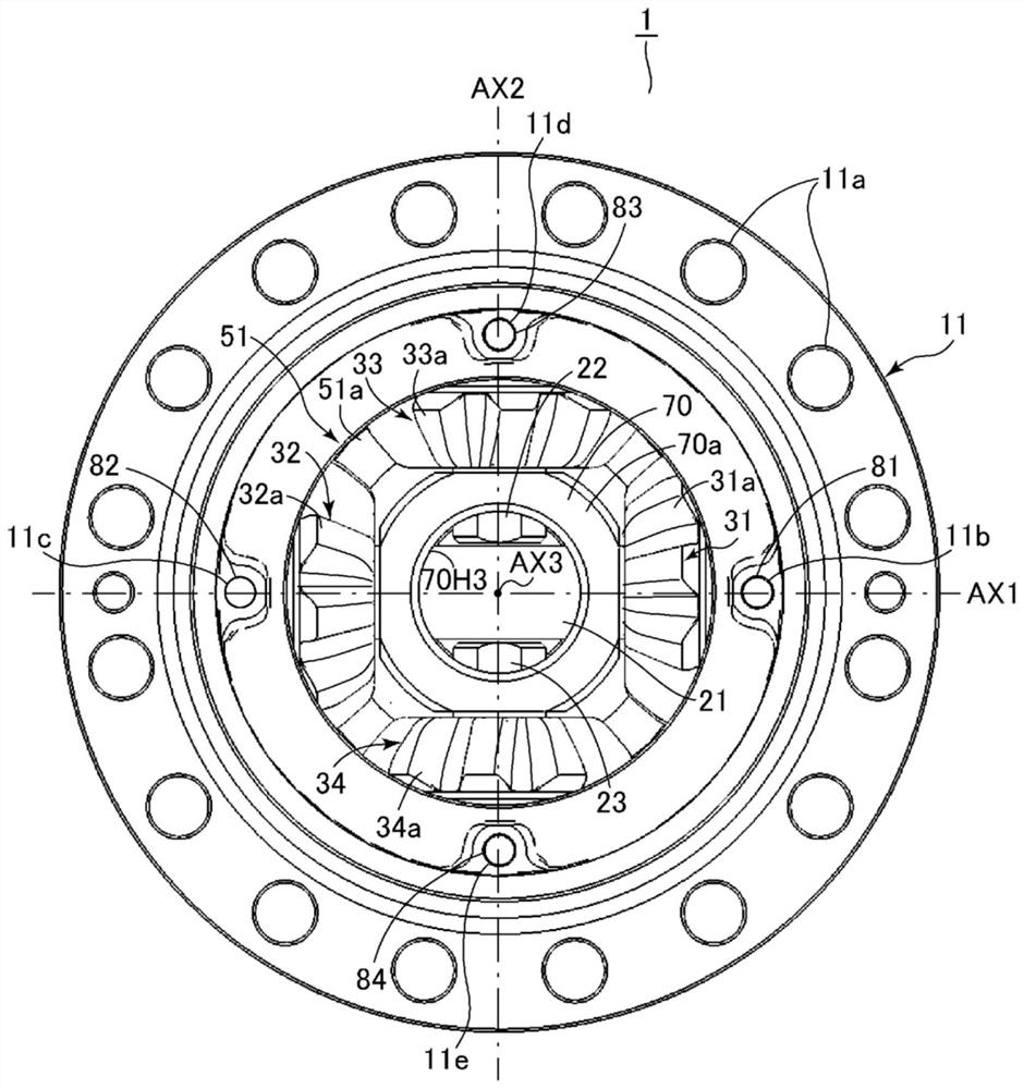
[0025] Below, use figure 1 This first embodiment will be described through FIG. 4 . figure 1 is a schematic diagram showing the drive system of the vehicle according to the present embodiment, figure 2 is a sectional view showing the differential device according to the present embodiment, image 3 is an axial view of a part of the differential case main body according to this embodiment viewed from the axial direction of the propeller shaft, Figure 4A is a schematic diagram showing the number of teeth of the first to fourth pinion gears and the second side gear according to the first embodiment, Figure 4B It is a figure explaining the vibration amplitude of the 2nd side gear with respect to a 2nd differential case concerning 1st Embodiment.
[0026] [Structure of vehicle drive system]
[0027] First, use figure 1 The configuration of the drive system of the vehicle 100 mounted on the differential device 1 according to the first embodiment will be described. Such as ...
no. 2 approach >
[0063] Next, regarding the second embodiment with partial changes to the above-mentioned first embodiment, use Figure 5 to explain. Figure 5 It is a schematic diagram showing the number of teeth of the first to fourth pinion gears and the second side gear according to the second embodiment. In addition, in the description of the second embodiment, the same reference numerals are attached to the same parts as those of the first embodiment described above, and description thereof will be omitted.
[0064] In the differential device 1 according to the second embodiment, the second side gear 52 is changed from that of the above-mentioned first embodiment. 2 number of teeth. That is, if Figure 5 As shown, likewise the second side gear 52 2 The number of teeth is 4N+2, which is an even number that is not a multiple of 4, and specifically the number of teeth is composed of 18. In addition, the first to fourth pinions 31 2 、32 2 、33 2 、34 2 The number of teeth is an odd nu...
PUM
 Abstract
Description
Claims
Application Information