Supercharge Your Innovation With Domain-Expert AI Agents!

Negative pressure drainage device

A negative pressure drainage and negative pressure technology, applied in the field of medical equipment, can solve the problems of cumbersome operation, failure to realize automatic conduction or isolation of the negative pressure ball and the discharge tube, and achieve the effect of convenient operation

Inactive Publication Date: 2021-04-30
ZHEJIANG PROVINCIAL PEOPLES HOSPITAL
View PDF0 Cites 0 Cited by
  • Summary
  • Abstract
  • Description
  • Claims
  • Application Information

AI Technical Summary

Problems solved by technology

[0003] A general negative pressure drainage device includes a negative pressure ball, a drainage tube, and a discharge tube. The negative pressure ball is respectively connected to the drainage tube and the discharge tube. Set the switch on the drain tube, insert the drain tube into the drainage place, flatten the negative pressure ball, close the switch on the drain tube to form a negative pressure, draw out the drainage fluid, and then turn on the switch to drain the drainage fluid from the discharge tube. The liquid pipe is discharged and collected. This kind of diverter is opened or closed by manually controlling the switch. The operation is cumbersome, and the automatic conduction or isolation of the negative pressure ball and the liquid discharge pipe cannot be realized.

Method used


Image

  • Negative pressure drainage device
  • Negative pressure drainage device

Examples


Embodiment Construction

[0015] A negative pressure drainage device of the present invention will be further described in detail below in conjunction with the accompanying drawings.

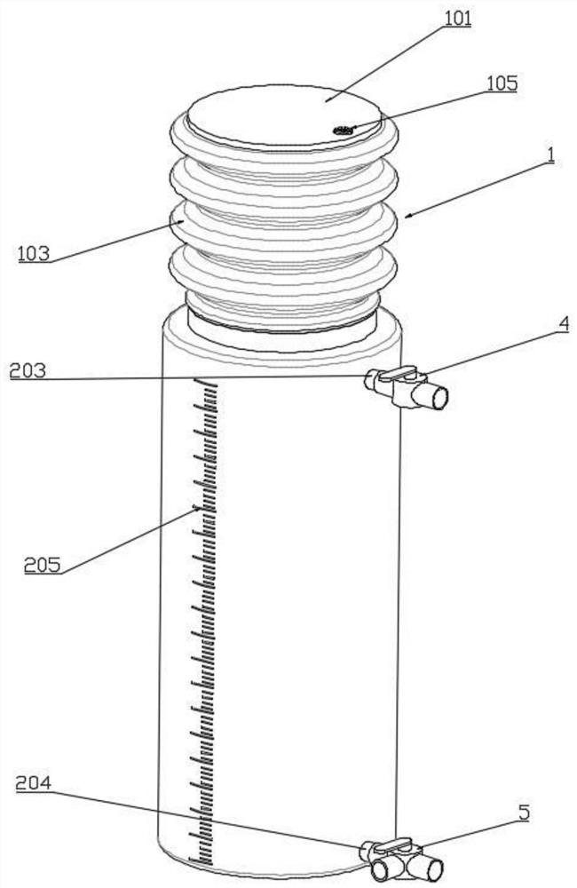
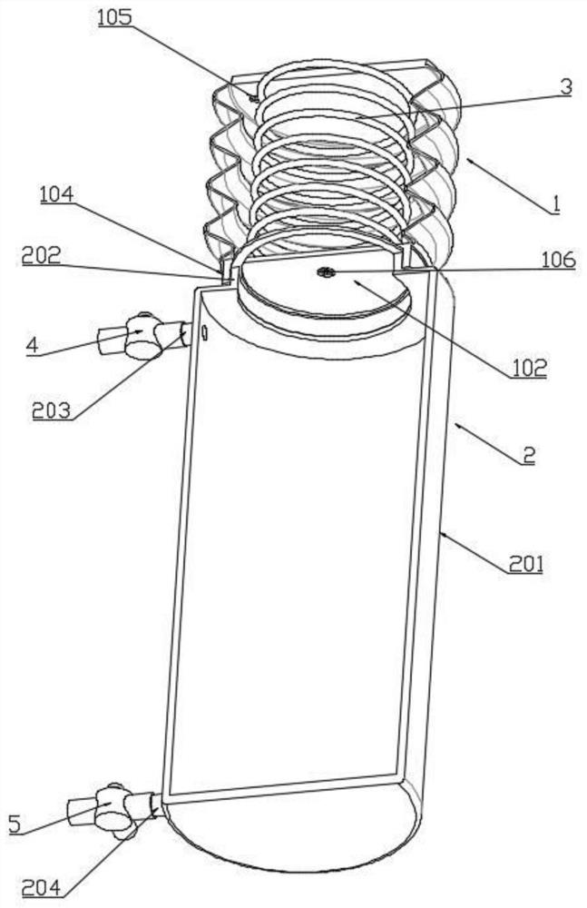
[0016] combined with figure 1 - attached figure 2 A negative pressure drainage device, comprising a negative pressure generating device 1 and a storage tank 2, the negative pressure generating device 1 is composed of a corrugated cylinder 103 and an upper plate 101 and a lower plate 102 arranged at both ends of the corrugated cylinder 103, the A return spring 3 is provided between the upper plate 101 and the lower plate 102, the upper plate 101 is provided with a first one-way valve 105, and the lower plate 102 is provided with a second one-way valve 106, the lower plate body 102 is provided with a first connecting ring 104 on the side away from the corrugated cylinder 103;

[0017] The mouth of the storage tank 2 is provided with a second connection ring 202 that is matched with the first connection ring 104, and the...


PUM


Abstract

The invention relates to the field of medical instruments, in particular to a negative pressure drainage device which comprises a negative pressure generating device and a storage tank, the negative pressure generating device is composed of a corrugated cylinder, an upper plate body and a lower plate body, the upper plate body and the lower plate body are arranged at the two ends of the corrugated cylinder, and a reset spring is arranged between the upper plate body and the lower plate body; a second one-way valve is arranged on the lower plate body, and a first connecting ring is arranged on the side, away from the corrugated cylinder, of the lower plate body; a second connecting ring connected with the first connecting ring in a matched mode is arranged at a tank opening of the storage tank, a pressure relief pipe is arranged at the end, close to the second connecting ring, of the side wall of the storage tank, and an inlet pipe is arranged at the position, close to the bottom of the tank body, of the side wall of the storage tank.

Description

technical field [0001] The invention relates to the field of medical equipment, in particular to a negative pressure drainage device. Background technique [0002] There are many types of surgical drainage tubes used clinically, and some are used for wounds, abdominal cavity, gastrointestinal tract, biliary tract, etc. Drainage after surgery is mainly to guide postoperative lacunar fluid or wound exudate out of the body to prevent Postoperative infection affects wound healing. During the drainage process, the effusion needs continuous and effective drainage, and it is necessary to prevent the backflow of the drainage fluid and cause infection. Therefore, negative pressure drainage devices are widely used. [0003] A general negative pressure drainage device includes a negative pressure ball, a drainage tube, and a discharge tube. The negative pressure ball is respectively connected to the drainage tube and the discharge tube. Set the switch on the drain tube, insert the dra...

Claims


Application Information

Patent Timeline
Patent Type & Authority Applications(China)
IPC IPC(8): A61M1/00
Inventor 王鹏
Owner ZHEJIANG PROVINCIAL PEOPLES HOSPITAL
Features
  • R&D
  • Intellectual Property
  • Life Sciences
  • Materials
  • Tech Scout
  • Unparalleled Data Quality
  • Higher Quality Content
  • 60% Fewer Hallucinations
Learn More