Cementing die and manufacturing method thereof

A mold manufacturing and mold technology, which is applied in the field of glued molds and its manufacturing, can solve problems such as difficult production, poor matching accuracy, and complex molds

Active Publication Date: 2021-04-30
AVIC BEIJING AERONAUTICAL MFG TECH RES INST
View PDF7 Cites 0 Cited by
  • Summary
  • Abstract
  • Description
  • Claims
  • Application Information

AI Technical Summary

Problems solved by technology

[0005] An embodiment of the present invention provides a bonding mold and a manufacturing method thereof. The first mold part is prepared according to the surface structure of the top plate inner surface, the bottom plate inner surface, and the web inner surface of the channel beam, and according to the inner surface of the channel beam top plate The second mold part is prepared according to the surface structure of the groove and the inner groove of the bottom plate, and the third mold part is manufactured according to the gap between the first mold part and the second mold part and the channel beam. The split mold assembly method can be used for different Orientation design of the mold for the surface or type of channel beam to solve the problems of complex mold, difficult production and poor matching accuracy in the forming process of the channel beam structure

Method used


Image

  • Cementing die and manufacturing method thereof
  • Cementing die and manufacturing method thereof

Examples


Embodiment Construction

[0026] Embodiments of the present invention will be further described in detail below in conjunction with the accompanying drawings and examples. The detailed description and accompanying drawings of the following embodiments are used to illustrate the principles of the present invention, but cannot be used to limit the scope of the present invention, that is, the present invention is not limited to the described embodiments, without departing from the spirit of the present invention Any modification, substitution and improvement of parts, components and connection methods are covered under.

[0027] It should be noted that, in the case of no conflict, the embodiments in the present application and the features in the embodiments can be combined with each other. The present application will be described in detail below with reference to the accompanying drawings and embodiments.

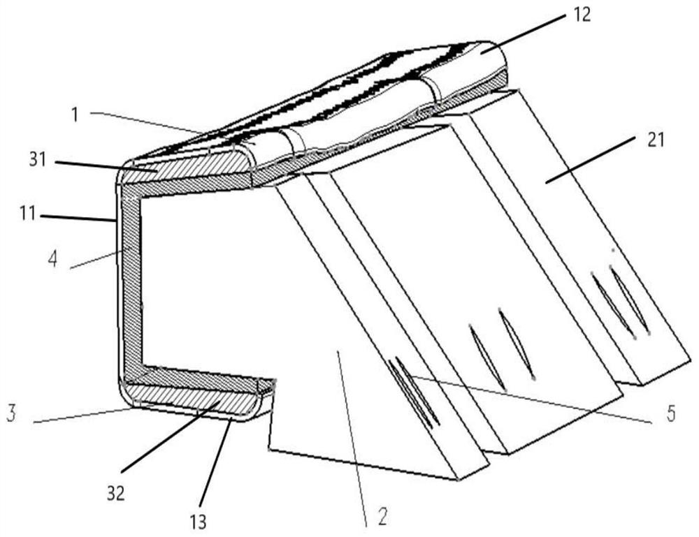
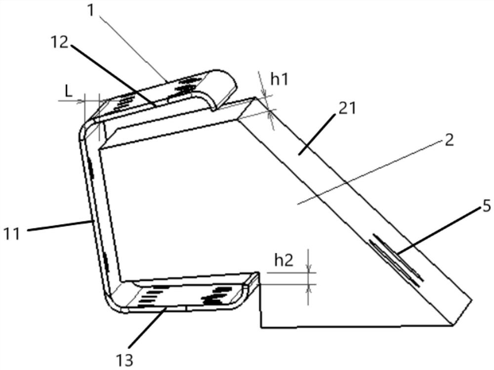
[0028] figure 1 It is a structural schematic diagram of a bonding mold according to an embodime...


PUM


Abstract

The invention relates to a cementing die. The cementing die is used for repairing and remanufacturing a closed channel beam structure, the closed channel beam structure comprises a channel beam, the channel beam comprises a web, a top plate and a bottom plate, the top plate and the bottom plate are connected to the two ends of the web separately, and grooves are formed in the bottom plate and the top plate. The cementing die comprises a first die part, a second die part and a third die part which are connected in a split mode, and the second die part comprises a lower filling block arranged in the groove of the bottom plate and an upper filling block arranged in the groove of the top plate separately. At least part of the first die part is located in a cavity defined by the web, the top plate and the bottom plate, and the third die part is filled in a gap formed by the first die part, the web, the top plate and the bottom plate in the cavity separately. A split type die assembly mode is adopted, so that die orientation design is carried out for channel beam structures with different molded surfaces or types, and the problems that in the forming process of a channel beam structure, a die is complex, the manufacturing difficulty is large, and the matching precision is poor are solved.

Description

technical field [0001] The invention relates to the field of metal structure bonding, in particular to a bonding mold and a manufacturing method thereof. Background technique [0002] With the continuous development of the aviation field and the continuous increase of the output of aviation products, the maintenance work after the product reaches the end of its life or after the product has a problem has become a more important process link and research direction. Remanufacturing has also become a new way of repairing aviation products. For the remanufacturing process of metal honeycomb sandwich components, due to the relatively simple surface of the skin and other materials and simple calculation, it is often possible to directly replace new parts, while the profile of the beam structure is complex, and in the absence of the original digital model, only In the process of repair and remanufacture by means of reverse modeling, the beam structure often needs to be preserved, ...

Claims


Application Information

Patent Timeline
IPC IPC(8): B21D3/16B21D37/20B21D53/92
CPCB21D3/16B21D37/20B21D53/92
Inventor 范雨娇宋旻键白树成蔡良元王新庆姜茂川曾安民斯奎朱慧斌
Owner AVIC BEIJING AERONAUTICAL MFG TECH RES INST
Why Eureka
Try Eureka