Deformed steel bar thermal diffusion treatment method and equipment
A technology for processing equipment and threaded steel, which is applied in the field of thermal diffusion processing methods and processing equipment for threaded steel, can solve problems such as deformation, and achieve the effect of being easy to pick and place.
- Summary
- Abstract
- Description
- Claims
- Application Information
AI Technical Summary
Problems solved by technology
Method used
Image
Examples
Embodiment 1
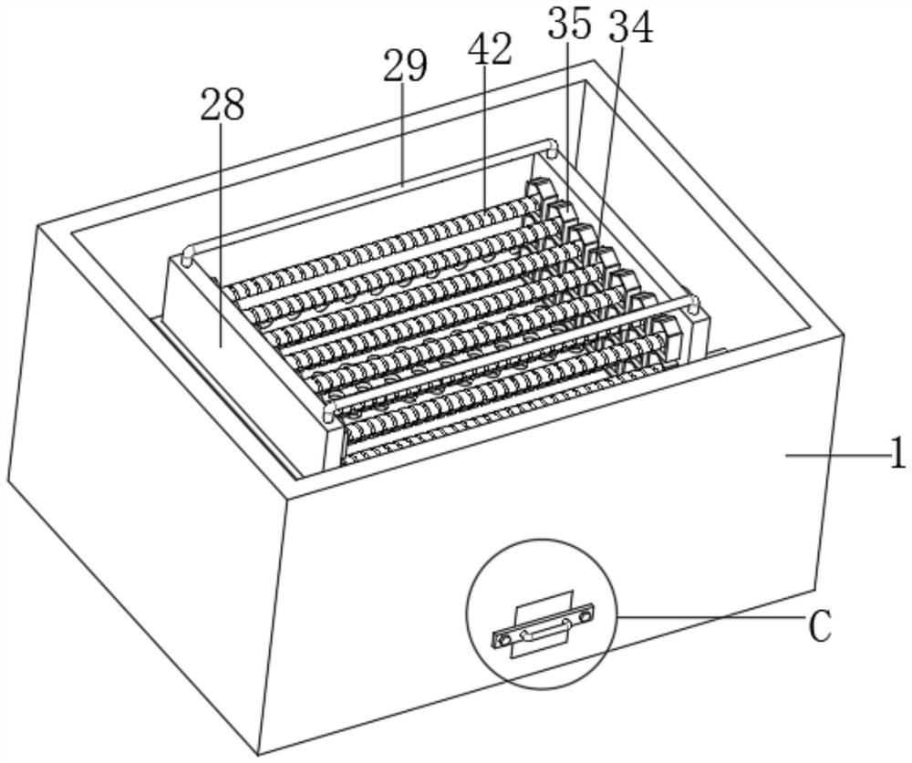
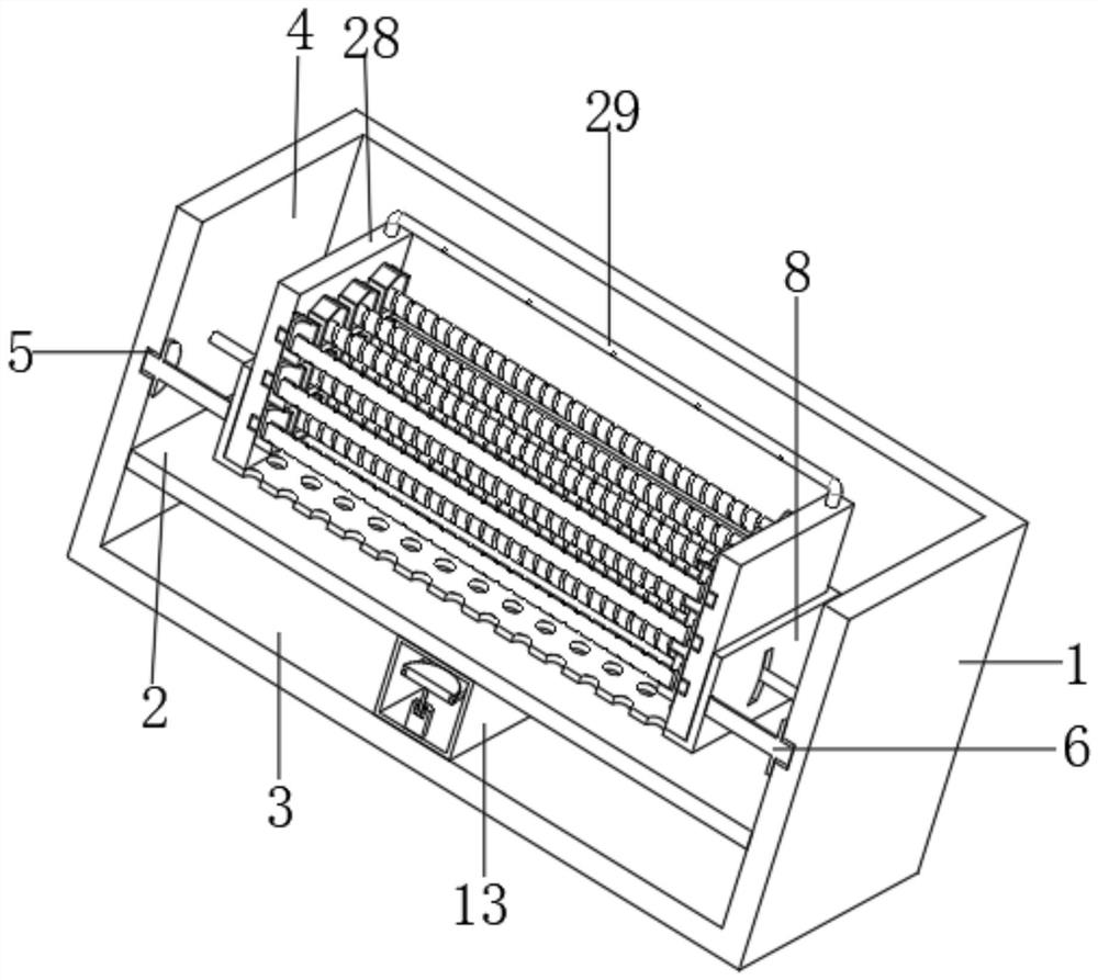
[0044] like figure 1 , figure 2 and image 3 As shown, the rebar thermal diffusion treatment equipment includes a salt bath 1 and a rebar 42. A partition 2 is fixed on the inner wall of the salt bath 1, and the partition 2 is fixed at a position lower than the center of the inner wall of the salt bath 1. The partition 2 covers the salt bath 1. Divided into heating zone 3 and diffusion zone 4,
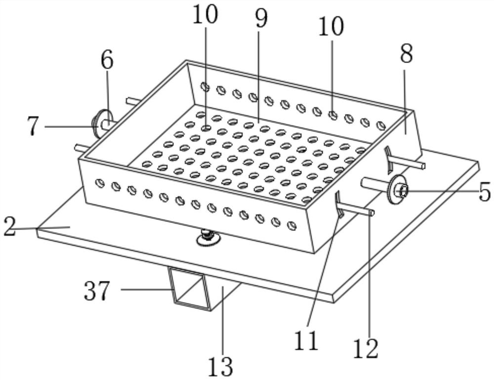
[0045] The inside of the diffusion area 4 is provided with a placing assembly, which includes a rotating bearing 5, a rotating rod 6, a protective ring 7, a placing body 8, a placing groove 9, a through hole 10, a supporting arc groove 11 and a supporting rod 12; the rotating bearing 5 is symmetrical Embedded on two opposite inner walls of the diffusion area 4, the horizontal plane where the rotary bearing 5 is embedded in the interior of the diffusion area 4 is lower than the horizontal plane where the center of the inner wall of the diffusion area 4 is located, and the rotating rod...
Embodiment 2
[0047] Embodiment 2 is a further improvement to Embodiment 1:
[0048] like Figure 4 , Figure 5 and Image 6 As shown, a heat insulation box 13 is arranged in the center of the heating zone 3, heating equipment is arranged inside the two areas separated by the heat insulation box 13 inside the heating zone 3, and an offset assembly is arranged inside the heat insulation box 13, and the offset assembly includes Servo motor 14, central pulley 15, side pulley 16, belt 17, supporting rotating rod 18, auxiliary bearing 19, driving rod 20, driving bearing 21, closed ring 22, driving thread 23, stop plate 24, spiral ring 25, connecting rod 26 and the top bar 27; the servo motor 14 is screwed and arranged at the bottom center of the heat insulation box 13 inner cavity, the center pulley 15 is connected with the output shaft of the servo motor 14, and the auxiliary bearing 19 is fixed at the bottom end of the heat insulation box 13 inner cavity to support the rotation Rod 18 is ro...
Embodiment 3
[0051] Embodiment 3 is a further improvement to embodiment 2:
[0052] like Figure 7 , Figure 8 , Figure 9 , Figure 10 and Figure 11 As shown, a holding assembly is installed in the placement groove 9, and the holding assembly includes side plates 28, U-shaped connecting rods 29, rope grooves 30, matching bearings 31, matching rotating rods 32, holding plates 33, and semi-cylindrical grooves 34 And baffle plate 35; Side plate 28 and U-shaped connecting rod 29 are all provided with two groups and two groups of side plates 28 are connected by two groups of U-shaped connecting rods 29, and the maximum horizontal distance between side plates 28 is equal to the length of placement groove 9 , the width of the side plate 28 is equal to the width of the placement groove 9, the height of the side plate 28 is greater than the depth of the placement groove 9, the rope grooves 30 are arranged at the center of the bottom end of the U-shaped connecting rod 29 at equal intervals, an...
PUM
 Abstract
Description
Claims
Application Information
 - R&D
- Intellectual Property
- Life Sciences
- Materials
- Tech Scout
- Unparalleled Data Quality
- Higher Quality Content
- 60% Fewer Hallucinations
Browse by: Latest US Patents, China's latest patents, Technical Efficacy Thesaurus, Application Domain, Technology Topic, Popular Technical Reports.
© 2025 PatSnap. All rights reserved.Legal|Privacy policy|Modern Slavery Act Transparency Statement|Sitemap|About US| Contact US: help@patsnap.com


