Electrolytic aluminum cell shell breaking device

A technology of a shelling device and an electrolytic aluminum tank, which is applied in the field of electrolytic aluminum, can solve the problems of affecting the feeding, slow start-up speed, and increase the dwell time of the shelling hammer, so as to improve the shelling effect, reduce the dwell time, and reduce the stickiness. Effect of Junction Electrolyte

Pending Publication Date: 2021-04-30
黄文强
View PDF10 Cites 0 Cited by
  • Summary
  • Abstract
  • Description
  • Claims
  • Application Information

AI Technical Summary

Problems solved by technology

[0003] However, the electrolytic aluminum shelling device in the prior art also has the following disadvantages. In order to improve the effect of shelling, many enterprises will increase the quality of the shelling hammer to improve the strength of shelling. Difficulty returning
The difficulty of returning the shelling hammer will cause the following problems: the return speed of the shelling hammer will be reduced, and the starting speed will be slow during the shelling process. These will increase the time the shelling hammer stays in the electrolytic solution, and the shelling hammer head is very easy. The electrolyte is bonded, and after repeated accumulation, the sticky bag of the hammer head becomes larger and larger, resulting in greater and greater resistance encountered during the shelling process, which may easily cause the electrolyte shell to fail to penetrate, affecting normal feeding. And the serious loss of the shelling hammer affects the quality and service life of the shelling hammer

Method used


Image

  • Electrolytic aluminum cell shell breaking device
  • Electrolytic aluminum cell shell breaking device
  • Electrolytic aluminum cell shell breaking device

Examples


Embodiment Construction

[0030] In order to make the purpose, technical solution and advantages of the present invention clearer, the technical solution of the present invention will be clearly and completely described below in conjunction with specific embodiments of the present invention and corresponding drawings. Apparently, the described embodiments are only some of the embodiments of the present invention, but not all of them. Based on the embodiments of the present invention, all other embodiments obtained by persons of ordinary skill in the art without making creative efforts belong to the protection scope of the present invention.

[0031] The technical solutions provided by various embodiments of the present invention will be described in detail below in conjunction with the accompanying drawings.

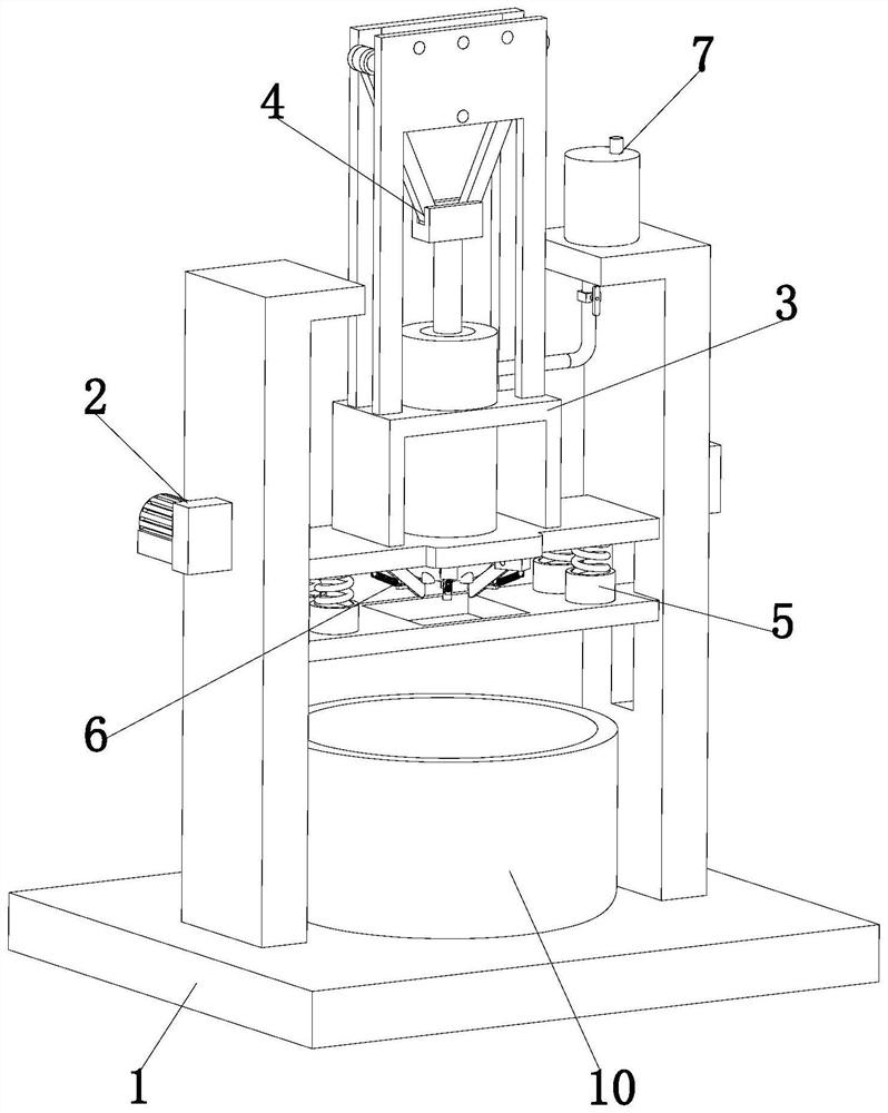
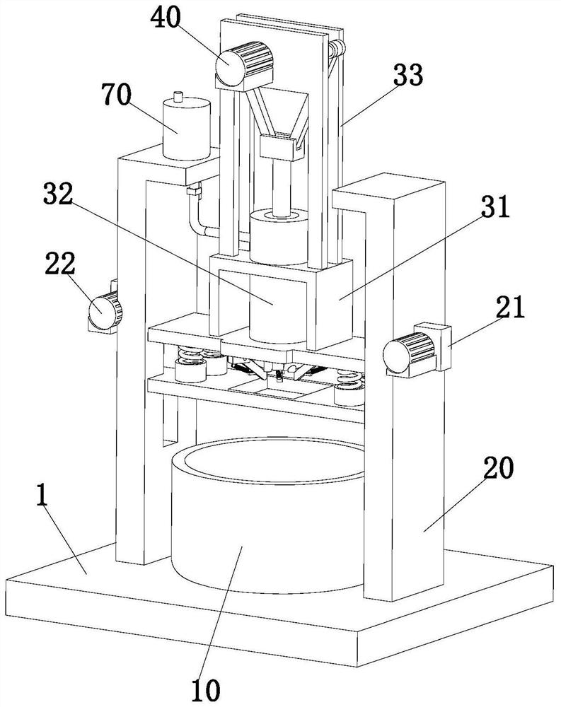
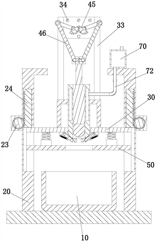
[0032] refer to Figure 1 to Figure 7As shown, the embodiment of the present invention provides a shelling device for an electrolytic aluminum tank, including a bottom plate 1, a lifting device ...


PUM


Abstract

The invention discloses an electrolytic aluminum cell shell breaking device, and belongs to the technical field of electrolytic aluminum. The device comprises a bottom plate, a lifting device, a bearing device, a shell breaking device, a buffer device, scraping devices and a feeding device, wherein the bottom plate is provided with an electrolytic cell with an upward opening, and the lifting device is arranged on the bottom plate; the bearing device is arranged right above the electrolytic cell and mounted on the lifting device, the shell breaking device is arranged on the bearing device, the buffer device is arranged above the electrolytic cell and mounted at the bottom of the bearing device, and the scraping devices are circumferentially distributed at the bottom of the bearing device. The feeding device is arranged on the lifting device and communicates with the bearing device. By means of mutual operation of all the devices, a mass shell in the electrolytic cell can be broken automatically and a material can be added automatically. Moreover, the shell breaking device can be scraped, so that the problem of affecting a subsequent shell breaking effect as an electrolyte is left on the shell breaking device is avoided.

Description

technical field [0001] The invention relates to the technical field of electrolytic aluminum, in particular to a device for shelling an electrolytic aluminum tank. Background technique [0002] In the process of aluminum production, the electrolytic aluminum tank is continuously produced, and alumina needs to be added to the electrolytic tank intermittently. In a high-temperature environment, a hard electrolyte shell will quickly form on the electrolyte solution, which hinders the input into the electrolytic tank. Alumina, therefore, a shell breaking device is required in the electrolytic aluminum tank feeding system to break the electrolyte shell. [0003] However, the electrolytic aluminum shelling device in the prior art also has the following disadvantages. In order to improve the effect of shelling, many enterprises will increase the quality of the shelling hammer to improve the strength of shelling. Difficulty returning. The difficulty of returning the shelling hamme...

Claims


Application Information

Patent Timeline
Patent Type & Authority Applications(China)
IPC IPC(8): C25C3/14
CPCC25C3/14
Inventor 黄文强
Owner 黄文强
Why Eureka
Try Eureka