An anchoring device for a cantilevered scaffold and its construction method

A technology of cantilevered scaffolding and anchoring device, which is applied to the accessories of scaffolding, scaffolding supported by house structure, construction, etc., can solve the problems of low utilization rate, lack of I-shaped steel reinforcement, and difficulty in taking out U-shaped bolts, etc.

Active Publication Date: 2021-09-14
YANJIAN GRP CO LTD
View PDF0 Cites 0 Cited by
  • Summary
  • Abstract
  • Description
  • Claims
  • Application Information

AI Technical Summary

Problems solved by technology

[0003] At present, when erecting cantilevered scaffolding, it is necessary to carry out anchoring work first, and the existing anchoring devices generally pre-embed U-shaped bolts on the pouring floor, and then use fastening nuts and other components to fix the I-shaped steel on the pouring floor. In this way, the anchoring work is completed, but it is difficult to take out the U-shaped bolts in the later stage of this anchoring method. When disassembling, it is necessary to use a cutting machine to cut off the extra U-shaped bolts, resulting in waste of steel, low utilization rate, and increased engineering. And there is a lack of reinforcement for I-shaped steel, which is prone to risks such as falling off

Method used


Image

  • An anchoring device for a cantilevered scaffold and its construction method
  • An anchoring device for a cantilevered scaffold and its construction method
  • An anchoring device for a cantilevered scaffold and its construction method

Examples


Embodiment Construction

[0028] The present invention will be further described below in conjunction with the examples.

[0029] The following examples are used to illustrate the present invention, but cannot be used to limit the protection scope of the present invention. The conditions in the embodiment can be further adjusted according to the specific conditions, and the simple improvement of the method of the present invention under the premise of the concept of the present invention belongs to the protection scope of the present invention.

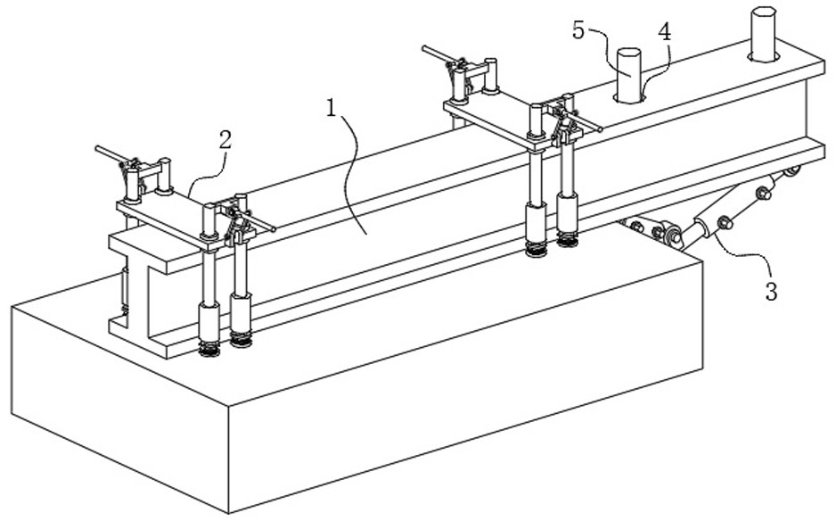
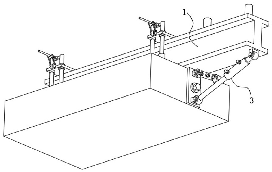
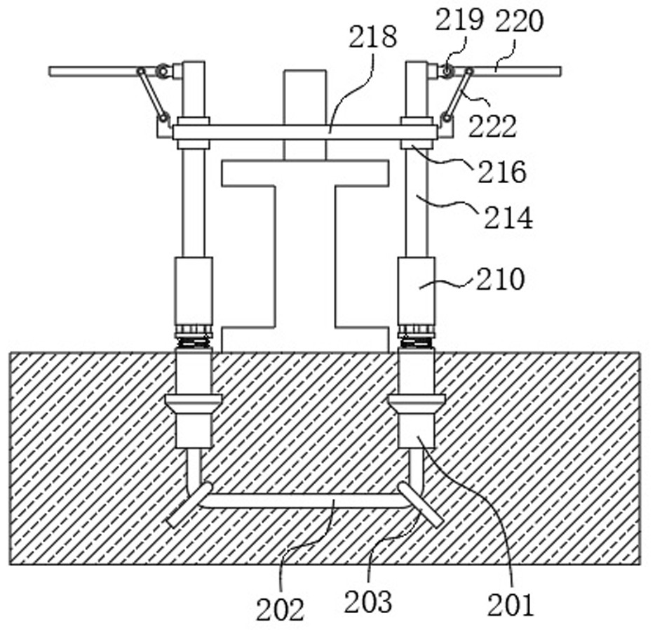
[0030] see Figure 1-6 , the present invention provides an anchoring device for a cantilevered scaffold, which includes an I-shaped steel 1 placed on the pouring floor. A reinforcement component 3 is installed between the bottom surface of one end on the outside of the floor and the side wall of the pouring floor. The fixing component 2 includes four threaded cylinders 201 pre-buried on the pouring floor. , the outer wall of the stud member 204 near the top ...


PUM


Abstract

The invention discloses an anchoring device for a cantilevered scaffold and a construction method thereof, belonging to the technical field of building construction, comprising an I-shaped steel placed on a pouring floor slab, and one end of the I-shaped steel deflecting to the inner side of the pouring floor slab is fixed on the inside of the pouring floor slab through two fixing components On the pouring floor, a reinforcing component is installed between the bottom surface of the I-shaped steel that is biased towards the outside of the pouring floor and the side wall of the pouring floor; after the rotating rod rotates 90°, the steel pressure plate just presses on the I-shaped steel, thereby completing the anchoring work. It is convenient and fast, and during the subsequent disassembly, except for the pre-embedded parts such as the threaded cylinder, other parts can be removed smoothly, which is convenient for repeated use, avoids the waste of excess steel, and does not need to be cut, which greatly reduces the amount of work and can be used for the project. The outer end of the section steel provides support and reinforcement to avoid safety risks such as shaking and falling off of the erected scaffolding. It can be adjusted according to the extension length of the outside of the I-section steel, and the adaptability is higher.

Description

technical field [0001] The invention belongs to the technical field of building construction, and in particular relates to an anchoring device for a cantilevered scaffold and a construction method thereof. Background technique [0002] Cantilevered scaffolding is a simple facility used in construction. It is divided into two types: one per floor and multi-layer cantilever. The method of erecting one per floor is: put the bottom of the pole on the floor, beam or wall, etc. After the building site is tilted outwards and fixed, set up crossbars and pave scaffolding boards on the upper part to form a construction layer. The construction is one layer high. Erection method: Divide the full-height scaffold into several sections, and the height of each section shall not exceed 20m. Use cantilevered beams or cantilever frames as the foundation of the scaffold to erect scaffolds in segments. Scaffolds exceeding 50m can be erected in this way. , the facade of the cantilevered scaffold...

Claims


Application Information

Patent Timeline
Patent Type & Authority Patents(China)
IPC IPC(8): E04G3/18E04G5/04
CPCE04G3/18E04G5/04
Inventor 张雷王向前纪赟珩王靖常峻玮王岩
Owner YANJIAN GRP CO LTD
Why Eureka
Try Eureka