Ball valve

A ball valve and valve body technology, applied in valve details, valve devices, valve operation/release devices, etc., can solve problems such as reduced service life, valve core damage, etc., to eliminate water hammer effect, facilitate rotation and valve core positioning Effect

Inactive Publication Date: 2021-04-30
何松
View PDF6 Cites 2 Cited by
  • Summary
  • Abstract
  • Description
  • Claims
  • Application Information

AI Technical Summary

Problems solved by technology

Ball valves are widely used. However, when the ball valve is closed in actual use, due to the sudden closure of the water flow, the cut-off water flow will have an impact on the valve core, commonly known as the "water hammer effect", which will cause damage to the valve core and reduce the valve core. service life

Method used


Image

  • Ball valve
  • Ball valve
  • Ball valve

Examples


Embodiment Construction

[0022] The technical solutions of the various embodiments of the present invention will be clearly and completely described below in conjunction with the accompanying drawings. Apparently, the described embodiments are only some of the embodiments of the present invention, not all of them. Based on the embodiments of the present invention, all other embodiments obtained by persons of ordinary skill in the art without creative work are within the protection scope of the present invention.

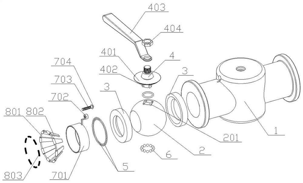
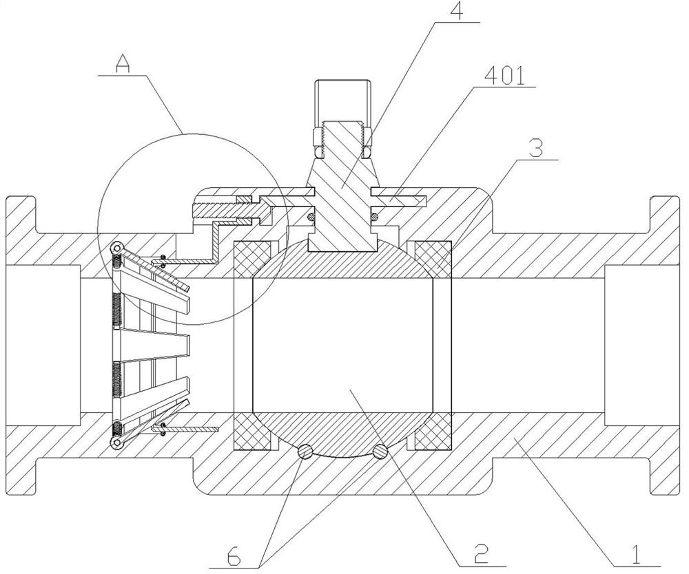
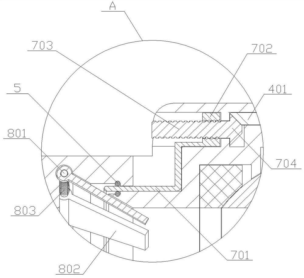
[0023] Example Figure 1 to Figure 6 As shown, a ball valve includes a valve body 1, a valve stem 4 and a valve core 2. The valve core 2 is located inside the valve body 1 and cooperates with the valve stem 4. A buffer is also installed inside the valve body 1. mechanism, the buffer mechanism includes a buffer component and a push mechanism, and the push mechanism includes a push plate 701 and a screw 703, and the screw 703 connects with the main bevel gear 704 installed on the end and the m...


PUM


Abstract

The invention discloses a ball valve. The ball valve comprises a valve body, a valve rod and a valve element, wherein the valve element is located in the valve body and matched with the valve rod, a buffering mechanism is further installed in the valve body, the buffering mechanism comprises a buffering component and a pushing mechanism, the pushing mechanism comprises a pushing plate and a lead screw, and the lead screw is matched with a main bevel gear arranged on the valve rod through an auxiliary bevel gear installed at the end. Under rotation of the valve rod, the lead screw is driven to rotate, and then the pushing plate is driven to push the buffering component to to be opened. The buffering component and the pushing mechanism are installed in the valve body, the main bevel gear on the valve rod drives the lead screw on the pushing mechanism to rotate, then the pushing plate is driven to move, and multiple buffering plates on the whole buffering component are driven to rotate around a connecting ring to be opened through movement of the pushing plate, so that when the valve is closed, the effect of buffering water flow is achieved to eliminate the water hammer effect; and meanwhile, balls arranged at the bottom of the valve element can facilitate rotation and positioning of the valve element.

Description

technical field [0001] The invention relates to the technical field of valves, in particular to a ball valve. Background technique [0002] As a pipeline seal, the ball valve is composed of a valve core, a valve body and a valve stem. The rotation of the valve stem drives the valve core to rotate in the valve body to open and close the internal pipeline of the valve body, which can be used for fluid adjustment and control. . Ball valves are widely used. However, when the ball valve is closed in actual use, due to the sudden closure of the water flow, the cut-off water flow will have an impact on the valve core, commonly known as the "water hammer effect", which will cause damage to the valve core and reduce the valve core. service life. Contents of the invention [0003] Aiming at the situation in the background technology, the present invention provides a ball valve, which effectively solves the problems in the background technology by setting a buffer plate to offset t...

Claims


Application Information

Patent Timeline
Patent Type & Authority Applications(China)
IPC IPC(8): F16K5/06F16K5/08F16K47/02F16K31/50F16K31/53F16K31/60
CPCF16K5/06F16K5/08F16K47/023F16K31/50F16K31/535F16K31/602
Inventor 何松
Owner 何松
Why Eureka
Try Eureka