Long-service-life offset type gear and rack pneumatic actuator

A pneumatic actuator, rack and pinion technology, applied in the direction of engine components, valve devices, mechanical equipment, etc., can solve the problems of accelerated wear of seals and guides, short service life of actuators, limited speed increase, etc., to improve the action Speed, increased service life, and reduced wear

Pending Publication Date: 2021-04-30
无锡福斯拓科科技有限公司
View PDF6 Cites 2 Cited by
  • Summary
  • Abstract
  • Description
  • Claims
  • Application Information

AI Technical Summary

Problems solved by technology

[0002] When the valve is used, it is usually equipped with an actuator to open and close the valve. Due to the structure of the traditional rack and pinion pneumatic actuator, the force applied by the compressed gas to the piston is different from the force generated by the meshing point of the rack and pinion. Overlap, during the action of the actuator, the piston is subjected to lateral force caused by the misalignment of the above two forces. Long-term use will accelerate the wear of the seal and guide, resulting in a shorter service life of the actuator
In addition, the air inlet and outlet of the traditional rack-and-pinion pneumatic actuator are limited by the structure of the cylinder body and cannot be enlarged, which leads to the unsatisfactory working conditions of some valves that require fast action or the speed increase is limited.

Method used


Image

  • Long-service-life offset type gear and rack pneumatic actuator
  • Long-service-life offset type gear and rack pneumatic actuator
  • Long-service-life offset type gear and rack pneumatic actuator

Examples


Embodiment Construction

[0022] The specific implementation manner of the present invention will be described below in conjunction with the accompanying drawings.

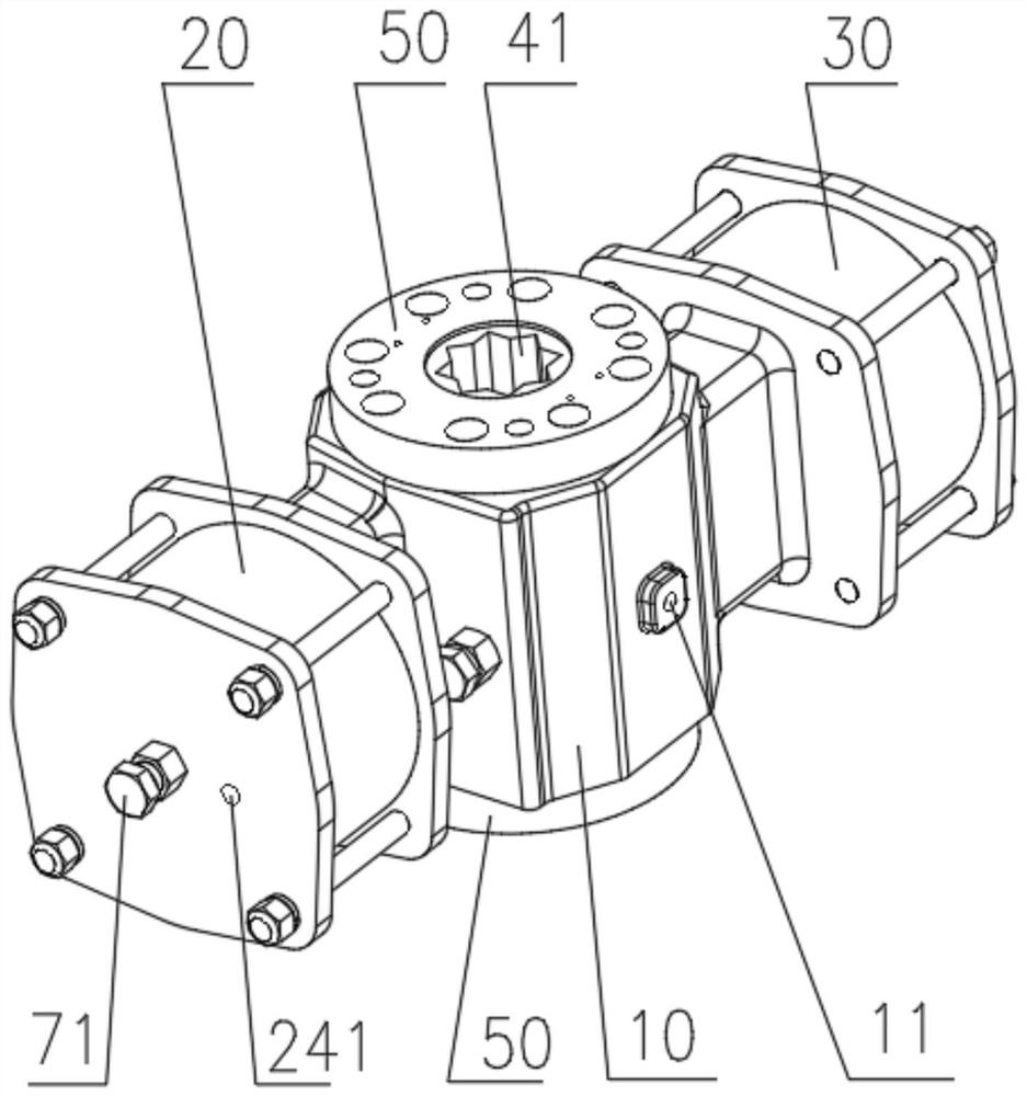
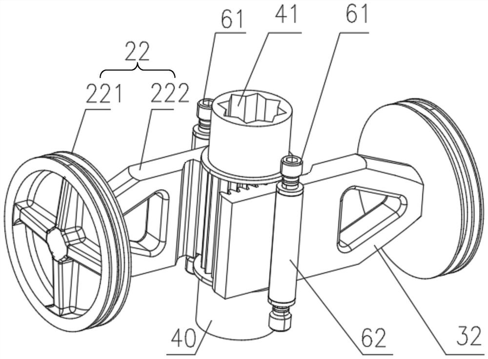
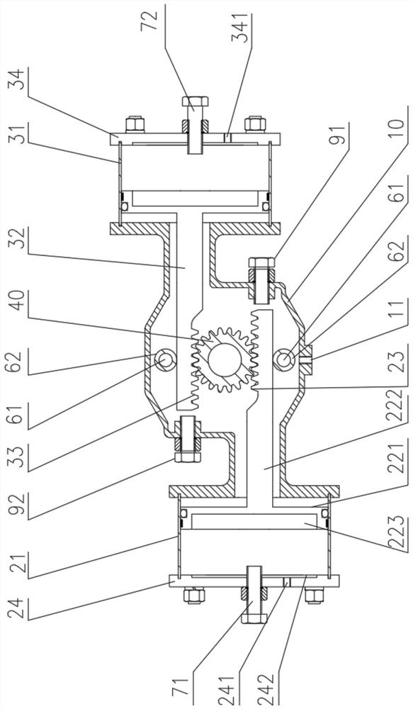
[0023] like Figure 1-4 As shown, the high-life offset rack and pinion pneumatic actuator of the present embodiment includes a cylinder one 20, a cylinder two 30 and a box body 10, and a left opening, a right opening and two opposite openings are provided on the box wall of the box body 10. The upper opening and the lower opening, the upper opening and the lower opening of the box body 10 respectively fix the flange 50, the cylinder body-21 of the cylinder-20 is fixed at the left opening of the box body 10, and the piston rod-22 of the cylinder-20 overhangs To the inside of the casing 10, the piston rod one 22 is provided with the rack one 23, the cylinder body two 31 of the cylinder two 30 is fixed on the right opening of the casing 10, and the piston rod two 32 of the cylinder two 30 extends to the casing 10 The inside of the piston rod...


PUM


Abstract

The invention relates to the technical field of valve process control, in particular to a long-service-life offset type gear and rack pneumatic actuator. The long-service-life offset type gear and rack pneumatic actuator is characterized in that a cylinder block I of a cylinder I is fixed to a left opening of a box body; a rack I is arranged on a piston rod I of the cylinder I; a cylinder block II of a cylinder II is fixed to a right opening of the box body; a rack II is arranged on a piston rod II of the cylinder II; the two ends of a gear shaft in the box body are rotationally inserted into two flanges respectively; one end of the gear shaft is used for being connected with a valve rod of a valve; the rack I and a rack II are meshed with the gear shaft respectively; an air port I is formed in the box wall of the box body; an air port II is formed in a cylinder cover I of the cylinder I; and an air port III is formed in a cylinder cover II of the cylinder II. When the box body is inflated or exhausts air outwards through the air port I, the piston rod I and the piston rod II move to drive the gear shaft to rotate in two different directions so as to drive the valve rod to rotate to achieve opening or closing of the valve. According to the long-service-life offset type gear and rack pneumatic actuator, long service life is achieved, the action speed is increased, one machine has a plurality of purposes, and batch production is facilitated.

Description

technical field [0001] The invention relates to the technical field of valve process control, in particular to a high-life offset rack and pinion pneumatic actuator. Background technique [0002] When the valve is used, it is usually equipped with an actuator to open and close the valve. Due to the structure of the traditional rack and pinion pneumatic actuator, the force applied by the compressed gas to the piston is different from the force applied at the meshing point of the rack and pinion. Overlap, during the action of the actuator, the piston is subjected to lateral force caused by the misalignment of the above two forces. Long-term use will accelerate the wear of the seal and guide, resulting in a shorter service life of the actuator. In addition, the air inlet and air outlet of the traditional rack and pinion pneumatic actuator are limited by the structure of the cylinder body and cannot be enlarged. As a result, some operating conditions where the valve needs to mov...

Claims


Application Information

Patent Timeline
Patent Type & Authority Applications(China)
IPC IPC(8): F16K31/122F16K31/54
CPCF16K31/1225F16K31/54
Inventor 姜国微王利敏
Owner 无锡福斯拓科科技有限公司
Why Eureka
Try Eureka