Drive unit for actuators in a motor vehicle

Inactive Publication Date: 2011-08-09
ROBERT BOSCH GMBH
View PDF24 Cites 2 Cited by
  • Summary
  • Abstract
  • Description
  • Claims
  • Application Information

AI Technical Summary

Benefits of technology

[0004]The device in accordance with the invention has the advantage that holes formed on the first part of the housing can simultaneously be used to accommodate the connecting elements and to accommodate the centering pins of the second housing part. As a result, an additional procedural step to attach the centering bore holes is eliminated. In addition, with this arrangement the diameter of

Problems solved by technology

Forming the centering pins and the centering bore hole is associated with an additional processing step, which is quite expensive especially if the pole pot is made of metal.
I

Method used


Image

  • Drive unit for actuators in a motor vehicle
  • Drive unit for actuators in a motor vehicle
  • Drive unit for actuators in a motor vehicle

Examples


Embodiment Construction

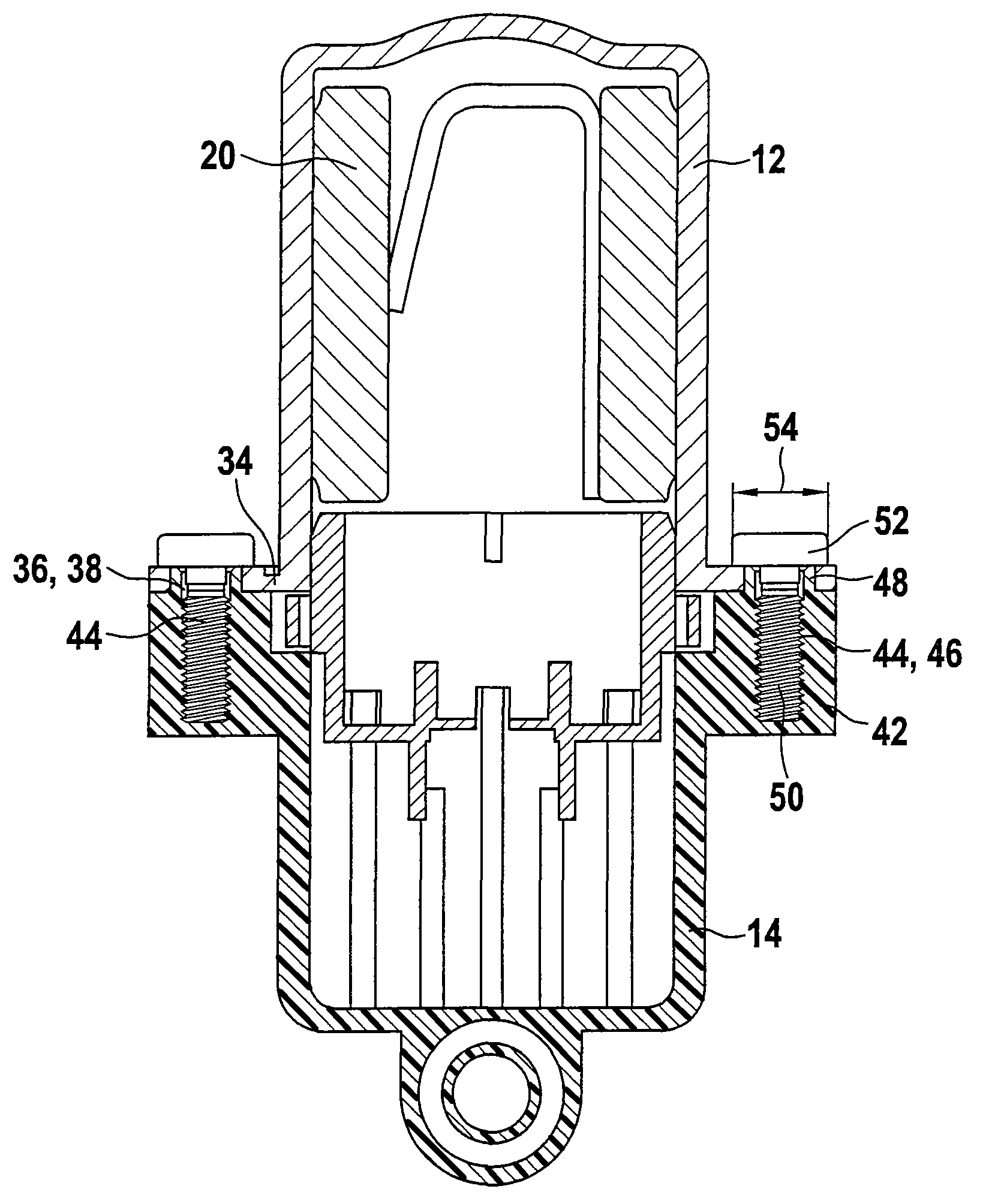
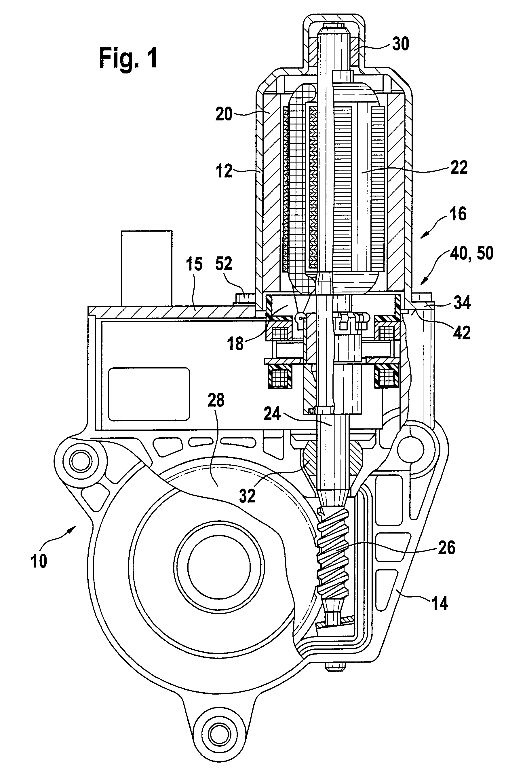
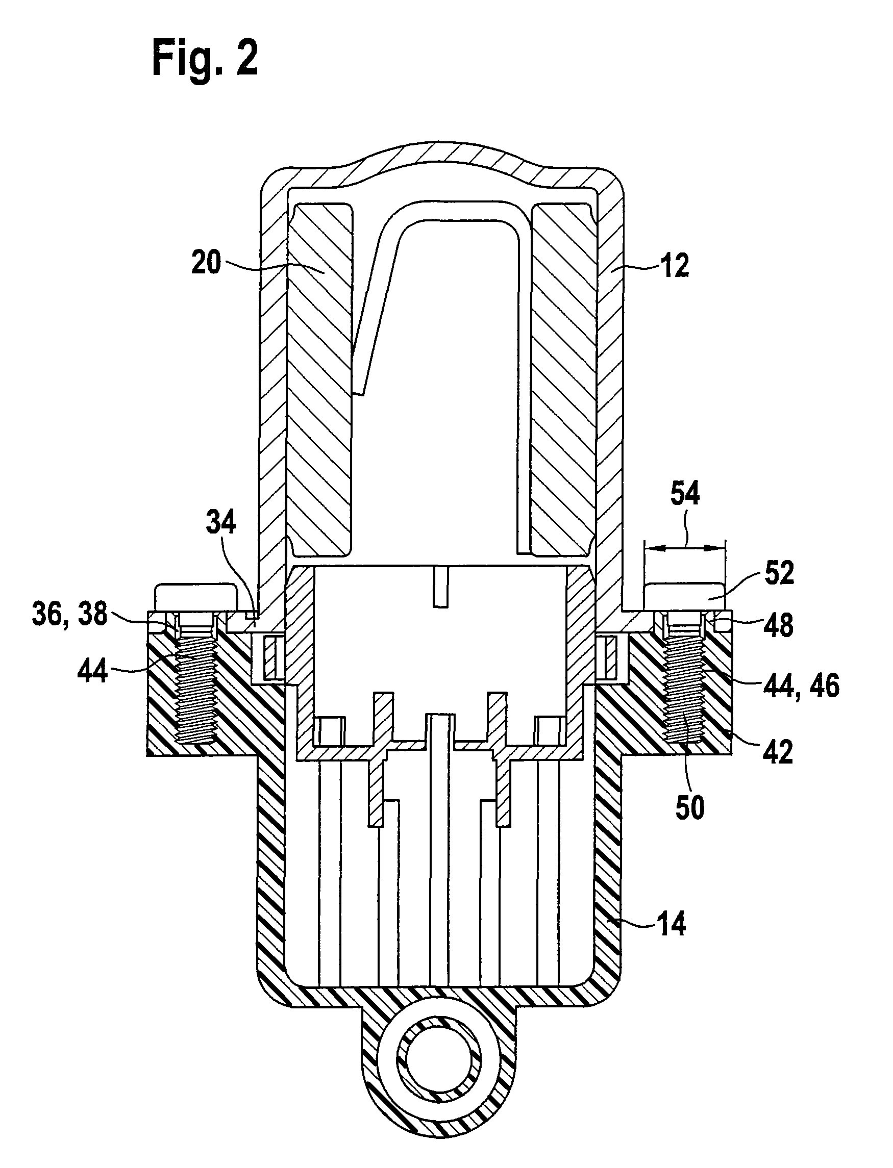
[0022]The exemplary embodiment depicted in FIG. 1 shows a drive unit 10 in accordance with the invention, wherein a first housing part 12 is embodied as a pole pot of an electric motor 16 and a second housing part 14 is embodied as a gear housing. Arranged between the first and second housing part 12, 14 is a brush holder 18, which, in an alternative execution, can also be embodied as another housing part 14. Permanent magnets 20 are arranged in the first housing part 12, which cooperate with an armature 22 of the electric motor 16. The electric motor 16 features an armature shaft 24 that extends through the brush holder 18 into the gear housing 14. A worm 26 that engages in a worm wheel 28 is arranged on the armature shaft 24. The armature shaft 24 is positioned, on the one hand, in the first housing part 12 by means of a cylinder bearing 30, for example, and in the second housing part 14 by means of a spherical cap bearing 32, for example. An electronic housing 15 is integrated in...


PUM


Abstract

A drive unit (10) actuates drives in a motor vehicle with a first housing part (12), in particular a pole pot (12), and a second housing part (14), in particular a gear housing or electronic housing (14, 15), which can be connected with connecting elements (40), wherein the first housing part (12) features receptacles (38) for the connecting elements (40), wherein the receptacles (38) are embodied as centering holes (36) for corresponding centering pins (48), which are arranged on the second housing part (14).

Description

BACKGROUND OF THE INVENTION[0001]The invention concerns a drive unit, in particular for actuating drives in a motor vehicle.[0002]A window lifter drive became known from WO 01 / 61133 whose housing includes a pole pot and a housing terminating the pole pot. In this case, the housing terminating the pole pot is a gear housing with an integrated electronic housing, wherein a separate component is arranged between the two parts of the housing as a brush holder that simultaneously serves as seal between the parts of the housing. The pole pot is composed of a deep-drawn, smoothed-down, cylindrical tube on whose open end a flange is formed in which holes to accommodate screws are left open. Formed in the flange of the gear housing are pocket threads into which the screws are screwed thereby solidly connecting the two parts of the housing with one another.[0003]In the case of such types of housings, centering bore holes are normally also attached on a flange for the purpose of centering the ...

Claims


Application Information

Patent Timeline
IPC IPC(8): F16H57/02F16H57/04F16H61/00F16B37/04H02K5/00E05F15/16H02K7/116
CPCH02K5/00H02K7/1166E05Y2900/55E05F15/697Y10T403/1683Y10T74/2186Y10T403/64F16B2200/50H02K7/116
Inventor HAUSSECKER, WALTERFREUND, STEFANHUCK, THOMASOCHS, MARKUS
Owner ROBERT BOSCH GMBH
Why Eureka
Try Eureka