
A system and method for controlling the temperature of an environmental wind tunnel test chamber

A wind tunnel test and environmental technology, applied in aerodynamic test, vehicle test, machine/structural component test, etc., can solve the problems of low temperature control accuracy, inability to meet the test requirements of new energy vehicles, long response time, etc. , to achieve the effects of clear and simple logical structure, strong engineering implementability and high economy

Active Publication Date: 2021-08-24
北京朗信智能科技有限公司
View PDF9 Cites 0 Cited by
  • Summary
  • Abstract
  • Description
  • Claims
  • Application Information

AI Technical Summary

Problems solved by technology

The new energy vehicle wind tunnel environmental test chamber is used to simulate the real climate environment in nature, and is used to verify the matching development and performance of the vehicle, air conditioning system, battery module, and motor drive system. The temperature control range of the wind tunnel environmental test chamber requires a wide range , and the system exhibits a large inertia hysteresis characteristic. However, the temperature control accuracy of the traditional wind tunnel environmental test chamber is low, and the response time is long, which cannot meet the test requirements of new energy vehicles.

Method used


Image

  • A system and method for controlling the temperature of an environmental wind tunnel test chamber
  • A system and method for controlling the temperature of an environmental wind tunnel test chamber
  • A system and method for controlling the temperature of an environmental wind tunnel test chamber

Examples


Embodiment Construction

[0051]Example embodiments will now be described more fully with reference to the accompanying drawings. Example embodiments may, however, be embodied in many forms and should not be construed as limited to the embodiments set forth herein; rather, these embodiments are provided so that this disclosure will be thorough and complete, and will fully convey the concept of example embodiments to those skilled in the art. The same reference numerals in the drawings denote the same or similar structures, and thus their detailed descriptions will be omitted.

[0052] In the following description of various examples of the invention, reference is made to the accompanying drawings, which form a part hereof, and in which are shown by way of illustration various exemplary structures, systems and steps which may implement aspects of the invention. It is to be understood that other specific arrangements of components, structures, exemplary means, systems and steps may be utilized and struc...


PUM


Abstract

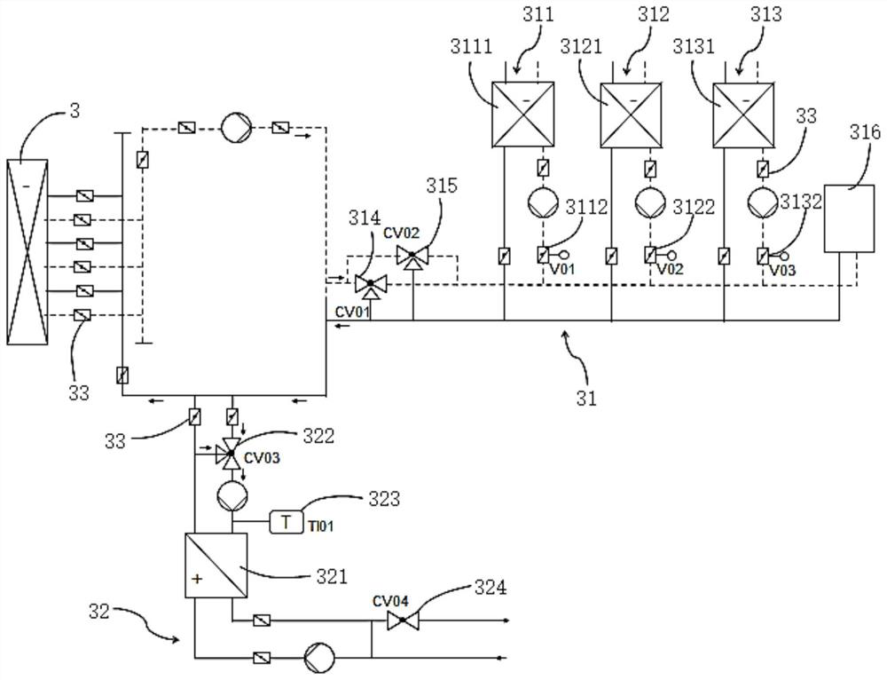
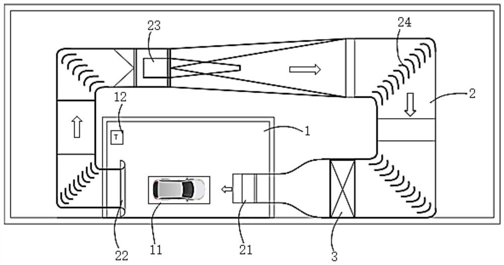
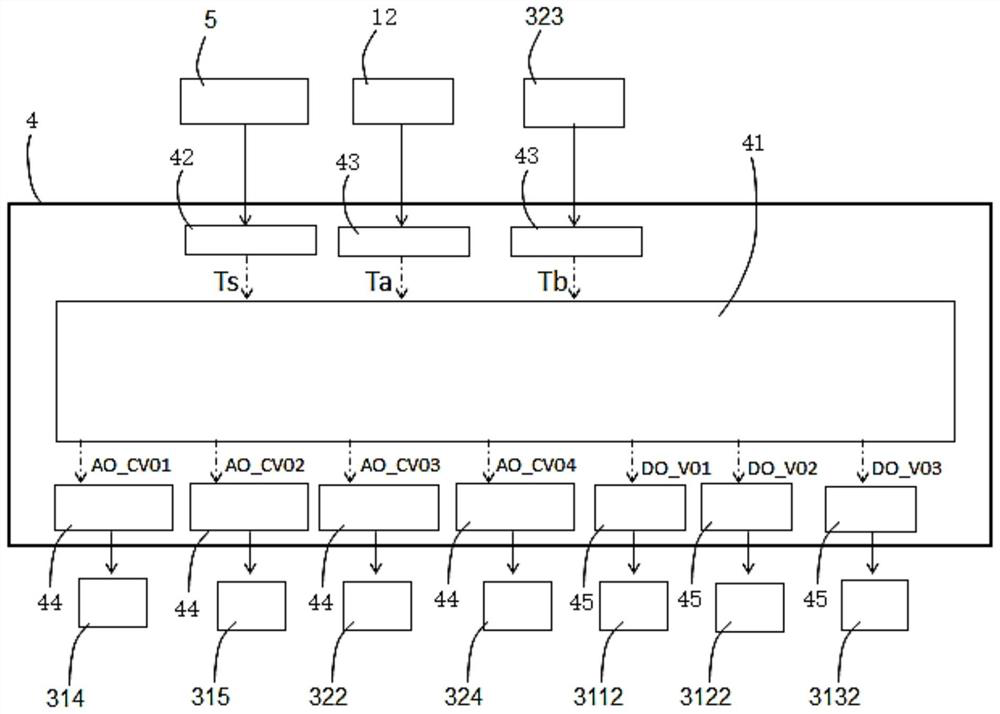
The invention discloses a system and method for regulating the temperature of an environmental wind tunnel test cabin. The system includes a main heat exchanger, a cooling pipeline and a heating pipeline, and the cooling pipeline and the heating pipeline are connected in parallel between the inlet and outlet of the main heat exchanger ; The cooling pipeline includes the first cooling branch, the second cooling branch and the third cooling branch arranged in parallel, which exchange heat with the exchangers circulating cooling water, frozen water and deep cooling water respectively; the first cooling branch The first on-off valve is set on the cooling line, the second on-off valve is set on the second cooling branch, and the third on-off valve is set on the third cooling branch; the first three-way regulating valve and the second three-way regulating valve are arranged in parallel on the cooling line. valve; the heating pipeline is provided with a third three-way regulating valve. The method of the present invention is applied to the system described above. The invention significantly improves the control accuracy level and response speed of the temperature regulation of the environmental wind tunnel test chamber, and the system and method of the application have a clear and simple logical structure, high reliability, and strong engineering implementability.

Description

technical field [0001] The present invention generally relates to the field of new energy vehicle environmental wind tunnel test chambers, and specifically relates to a system and method for regulating the temperature of an environmental wind tunnel test chamber. Background technique [0002] As consumers have higher and higher requirements for car functionality, comfort, and personalized experience, as well as the market demand for new energy Internet car companies to quickly update and iterate products, new energy car companies have gradually realized the self-owned car environment. The importance of the wind tunnel test chamber. The new energy vehicle wind tunnel environmental test chamber is used to simulate the real climate environment in nature, and is used to verify the matching development and performance of the vehicle, air conditioning system, battery module, and motor drive system. The temperature control range of the wind tunnel environmental test chamber require...

Claims


Application Information

Patent Timeline
Patent Type & Authority Patents(China)
IPC IPC(8): G01M9/04G01M17/007
CPCG01M9/04G01M17/007
Inventor 滕海石
Owner 北京朗信智能科技有限公司
Learn More