
Multifunctional electronic device test fixture

A technology for electronic devices and test fixtures, which is applied in the parts, instruments, and measuring devices of electrical measuring instruments, and can solve the problems of incompatibility, waste of resources, and inability to be generalized.

Pending Publication Date: 2021-04-30
深せん市奥达电源科技有限公司
View PDF0 Cites 3 Cited by
  • Summary
  • Abstract
  • Description
  • Claims
  • Application Information

AI Technical Summary

Problems solved by technology

In the traditional transformer coupling fixture, there is a single type of transformer corresponding to a coupling fixture. There is no way to use it universally. Not only can it not be used universally, but it also wastes too many resources.

Method used


Image

  • Multifunctional electronic device test fixture
  • Multifunctional electronic device test fixture
  • Multifunctional electronic device test fixture

Examples


Embodiment Construction

[0034] In order to describe the technical content, structural features, achieved goals and effects of the present invention in detail, the following will be described in detail in conjunction with the embodiments and accompanying drawings.

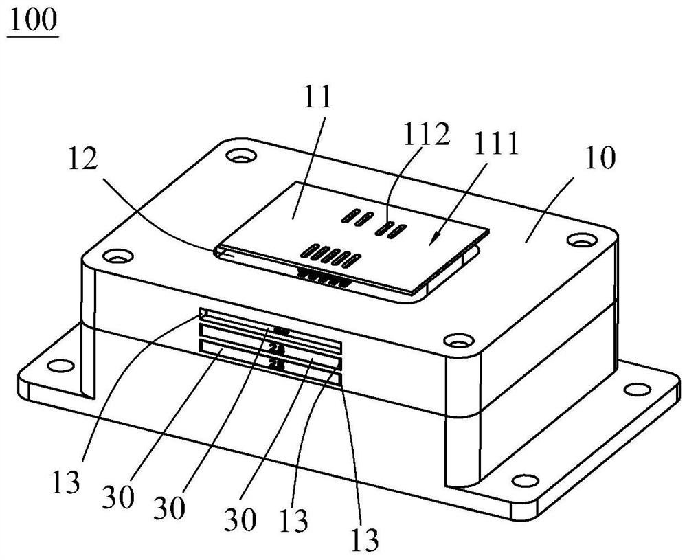
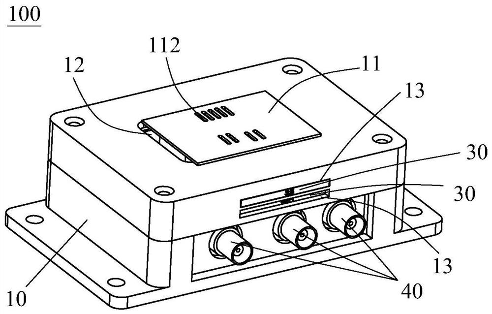
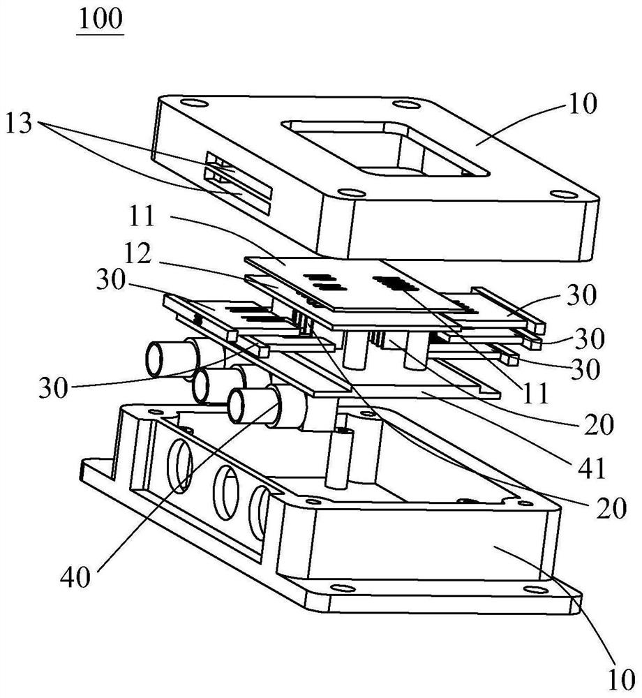
[0035] refer to Figure 1 to Figure 3 , the present invention discloses a multifunctional electronic device testing fixture 100, including a housing 10, a conductive terminal structure, a terminal positioning structure and a detection interface 40, the housing 10 includes a positioning table 11 for supporting or fixing an electronic device, and the positioning A plurality of sockets 112 for inserting the pins of the electronic device are opened on the insertion surface 111 of the platform 11 facing the pins of the electronic device. The conductive terminal structure has a plurality of conductive terminals 20 that are set at the corresponding positions of the jack 112 and can be matched with the pins inserted into the jack 112. The terminal...


PUM


Abstract

The invention discloses a multifunctional electronic device test fixture, which comprises a shell, the shell comprises a positioning table for supporting an electronic device, an insertion hole of a pin is formed in the insertion surface of the positioning table, a conductive terminal matched with the pin is arranged in the insertion hole, and at least one conductive terminal is a movable terminal. The movable terminal is slidably installed on the shell along a first direction parallel to the plugging surface. Each movable terminal corresponds to at least one positioning plugboard, the positioning plugboard comprises a movable clamping groove which corresponds to the position of the movable terminal and can be matched with the movable terminal in an inserted mode, an inserting groove for the positioning plugboard to be inserted is formed in the position, corresponding to the movable terminal, of the shell, and the positioning plugboard is inserted into the slot so that the movable terminal can be inserted into the corresponding movable clamping groove to locate the position of the movable terminal in the first direction. Compared with the prior art, the movable terminal is fixed at the position matched with the pin of the electronic device by selecting the positioning plugboards of different specifications according to the electronic devices of different specifications, so that the movable terminal is applicable to the electronic devices of different specifications, high in universality and convenient to operate.

Description

technical field [0001] The invention relates to a testing jig for an electronic device, in particular to a jig for functional testing the pin insertion of the electronic device. Background technique [0002] First of all, the transformer is the transmission element of magnetic energy in the circuit. In the circuit design, generally only the magnetic parameter characteristics such as its inductance and coupling coefficient and loss parameters are considered. However, in order to better study the working state of the transformer under dynamic conditions, it is necessary to measure its dynamic characteristics. Between the primary and secondary sides of the transformer, the coupling capacitance determined only by physical structural parameters such as the relative area of ​​the windings and the insulation distance between the windings is called a structural capacitance. Considering the influence of the winding potential distribution when the actual transformer is working, the c...

Claims


Application Information

Patent Timeline
IPC IPC(8): G01R1/04
CPCG01R1/0416
Inventor 肖秋林胡隆彪王金标郭修根
Owner 深せん市奥达电源科技有限公司
Learn More