Anti-vibration mechanism for imaging device, optical system, camera, and electronic equipment

A camera device and optical system technology, applied to optics, cameras, printing devices, etc., can solve problems such as thinning, miniaturization, hindering drive, sinking, etc., to reduce design difficulty, suppress natural vibration, and facilitate centering Effect

Pending Publication Date: 2021-04-30
CHANGZHOU RAYTECH OPTRONICS CO LTD
View PDF18 Cites 1 Cited by
  • Summary
  • Abstract
  • Description
  • Claims
  • Application Information

AI Technical Summary

Problems solved by technology

[0005] However, for example, in optical systems such as small devices mounted on portable electronic devices, such as medium-range telephoto systems with long optical lengths, the hand-shake correction mechanism exists due to the length of the driving amount and the weight of the lens, and it is difficult to reduce the thickness of the integrated mechanism. , the topic of miniaturization
[0006] In addition, since the autofocus mechanism for adjusting the focus that is driven in the direction of the optical axis is integrated with the lens movement and hand-shake correction mechanism that drives the lens on a plane perpendicular to the optical axis, it is also necessary to suppress the respective Due to the adjustment of the inherent vibration mechanism and the centerin

Method used


Image

  • Anti-vibration mechanism for imaging device, optical system, camera, and electronic equipment
  • Anti-vibration mechanism for imaging device, optical system, camera, and electronic equipment
  • Anti-vibration mechanism for imaging device, optical system, camera, and electronic equipment

Examples


Embodiment Construction

[0094] Hereinafter, the present invention will be described in detail with reference to the drawings.

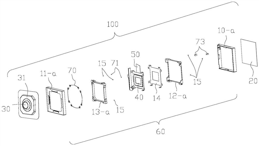
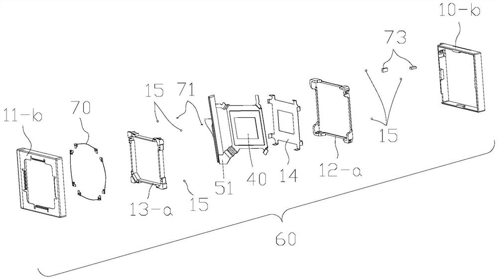
[0095] Figure 1 ~ Figure 4 It is a figure which shows the anti-vibration mechanism 100 for imaging devices of this invention, and the anti-vibration unit 60.

[0096] Figure 1 to Figure 12 An imaging device according to an embodiment of the present invention and its constituent elements are shown.

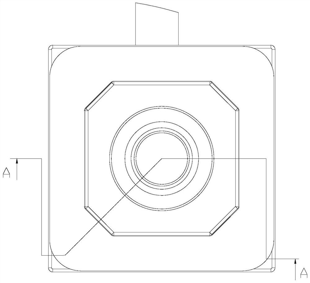
[0097] The imaging optical system of the anti-vibration mechanism 100 for an imaging device is composed of a lens 30, an autofocus mechanism 31 that drives the lens 30 and has a focus adjustment mechanism, or a telescopic zoom mechanism 32 that drives the lens 30 and includes a focus adjustment mechanism, and an imaging system from the object side. Optical system composed of elements 40.

[0098] The light beam from the subject that enters along the optical axis from the lens incident surface 30 - a of the lens 30 exits from the lens exit surface 30 - b and forms an image on...


PUM


Abstract

An anti-vibration mechanism for an imaging device is provided in an imaging device including a camera shake correction mechanism. Provided is an optical system which, in an imaging device provided with an optical system that moves in the direction of an optical axis and includes a focus adjustment mechanism, has an anti-vibration mechanism that performs camera shake correction by preventing vibration of an imaging element, and which, in order from the object side, is provided with an imaging lens group, an anti-vibration mechanism, and an imaging element on the anti-vibration mechanism. The image pickup element on the anti-vibration mechanism is rotated with respect to the optical axis of the image pickup lens group, and camera shake correction is performed.

Description

technical field [0001] The present invention relates to an anti-vibration mechanism for an imaging device with a hand shake correction function, an optical system, a camera and electronic equipment. Background technique [0002] With the rapid development of photographing technology, photographing devices including lens drive are widely used in a large number of photographing devices. Various portable electronic devices (such as cellular phones, tablet computers, etc.) employing lens-driven imaging devices are particularly popular with consumers. [0003] The driving mechanism of the lens driving device suitable for ordinary portable electronic equipment is generally composed of an autofocus mechanism that adjusts the focus in the direction of the optical axis and a hand-shake correction mechanism that drives in a plane perpendicular to the direction of the optical axis. [0004] These two functions are formed by a coil and a magnetic steel, and the coil is fixed on the per...

Claims


Application Information

Patent Timeline
IPC IPC(8): G03B5/00G02B7/09H04N5/232G03B30/00
CPCG03B5/00G02B7/09H04N23/687G03B30/00G03B2205/0038G03B2205/0069H04N23/54G03B3/10G03B2205/0046H04N23/55H04N23/57
Inventor 色摩和雄
Owner CHANGZHOU RAYTECH OPTRONICS CO LTD
Why Eureka
Try Eureka