Relay protection device

A relay protection and relay technology, applied in the direction of relays, electromagnetic relays, detailed information of electromagnetic relays, etc., can solve problems such as line influence, failure to remove dust from the relay box, and easy corrosion of dust

Inactive Publication Date: 2021-04-30
朱可欣
View PDF0 Cites 1 Cited by
  • Summary
  • Abstract
  • Description
  • Claims
  • Application Information

AI Technical Summary

Problems solved by technology

[0003] The invention provides a relay protection device to solve the technical problem in the prior art that dust cannot be removed inside the relay box, and the dust is easy to corrode the circuit and affect the service life of the relay

Method used

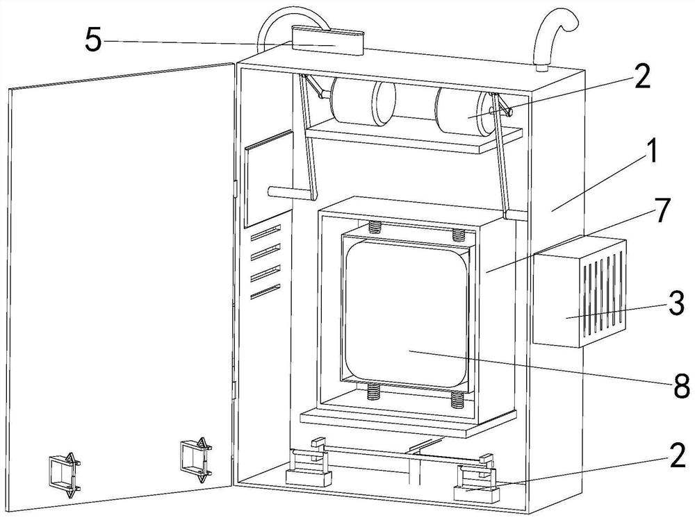
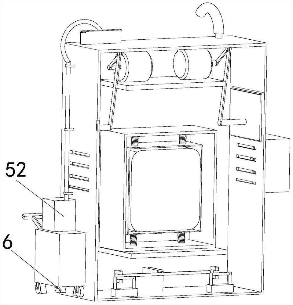
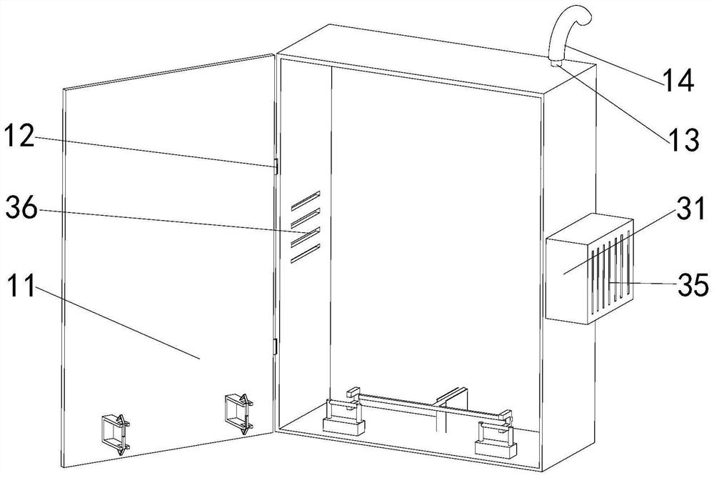

Image

  • Relay protection device
  • Relay protection device
  • Relay protection device

Examples


Embodiment Construction

[0027] The technical solutions of the present invention will be clearly and completely described below in conjunction with the accompanying drawings. Apparently, the described embodiments are part of the embodiments of the present invention, but not all of them.

[0028] The components of the embodiments of the invention generally described and shown in the figures herein may be arranged and designed in a variety of different configurations. Accordingly, the following detailed description of the embodiments of the invention provided in the accompanying drawings is not intended to limit the scope of the claimed invention, but merely represents selected embodiments of the invention.

[0029] Based on the embodiments of the present invention, all other embodiments obtained by persons of ordinary skill in the art without making creative efforts belong to the protection scope of the present invention.

[0030]In the description of the present invention, it should be noted that the ...


PUM


Abstract

The invention discloses a relay protection device, and relates to the technical field of relay protection devices. The device comprises a relay box body, a closing device, a heat dissipation device, a sealing device, a dust collection device, first self-locking universal wheels, a damping device and a relay, the relay box body is horizontally arranged, the closing device is arranged in the relay box body, the heat dissipation device is arranged outside one side of the relay box body, the sealing device is arranged in the relay box body, the dust collection device is arranged above the first self-locking universal wheels, the first self-locking universal wheels are horizontally arranged, the damping device is arranged in the relay box body, the relay is arranged in the damping device, and the temperature of the relay can be kept within a certain numerical value through a heat dissipation device so that the relay is not damaged, the service life is prolonged, a relay circuit can be prevented from being corroded after the interior of the relay box body is dedusted through the dust collection device, and the service life is prolonged.

Description

technical field [0001] The invention relates to the technical field of relay protection devices, in particular to a relay protection device. Background technique [0002] The relay is an electrical control device, which is an electrical appliance that causes the controlled quantity to undergo a predetermined step change in the electrical output circuit when the change of the input quantity meets the specified requirements. Usually used in automatic control circuits, it is actually an "automatic switch" that uses a small current to control the operation of a large current. Therefore, it plays the role of automatic adjustment, safety protection, and conversion circuit in the circuit. When applied to some large-scale equipment, due to the many and complex circuits, the relays are scattered throughout the equipment, which will bring great inconvenience to the maintenance and protection of the relays. If they are not protected in time, it is easy to affect the performance of the...

Claims


Application Information

Patent Timeline
IPC IPC(8): H01H50/04H01H50/02H01H50/12B08B1/00B08B5/04
CPCH01H50/04H01H50/023H01H50/12H01H50/02B08B5/04B08B1/30B08B1/12
Inventor 朱可欣
Owner 朱可欣
Why Eureka
Try Eureka