Use of natural gas for well enhancement

Active Publication Date: 2020-01-16
STABILIS ENERGY LLC
2 Cites 2 Cited by

AI-Extracted Technical Summary

Problems solved by technology

The flow of fluids out of the formation reduces formation pressure, however, and production eventually slows or ceases.
Liquids flowing into the well, which can include water an...

Benefits of technology

[0006]In some embodiments, regasified natural gas may be injected into a formation via one or more injection wells. The dry natural gas flows through the field absorbing liquids, increasing field pressure and lowering viscosity of liquids in the field. The wet natural gas can be produced through producing wells...

Abstract

A method for producing hydrocarbons includes the steps of a) providing a source of liquefied natural gas (LNG), b) regasifying the LNG at the well, c) pressurizing the regasified LNG above the formation pressure, d) injecting the pressurized LNG into the well, e) allowing the injection stream to flow into the producing formation, and f) recovering and transporting the regasified LNG and produced gas from the formation. The injection stream may include at least 85% methane and no more than 5 PPM water. Step f) may be carried out without separating the recovered gases. Step d) may continue for at least 24 hours. Step b) may comprise passing the LNG through a vaporizer. Step c) may be carried out before step b). An apparatus for injecting regasified LNG into a hydrocarbon formation may comprise an LNG tank, a vaporizer, a compressor, and a fluid connection to the producing formation.

Application Domain

Fluid removal

Technology Topic

EvaporatorMethane +3

Image

  • Use of natural gas for well enhancement
  • Use of natural gas for well enhancement

Examples

  • Experimental program(1)

Example

[0015]It is to be understood that the following disclosure provides different embodiments, or examples, for implementing different features of various embodiments. Specific examples of components and arrangements are described below to simplify the present disclosure. These are, of course, merely examples and are not intended to be limiting. In addition, the present disclosure may repeat reference numerals and/or letters in the various examples. This repetition is for the purpose of simplicity and clarity and does not in itself dictate a relationship between the various embodiments and/or configurations discussed.
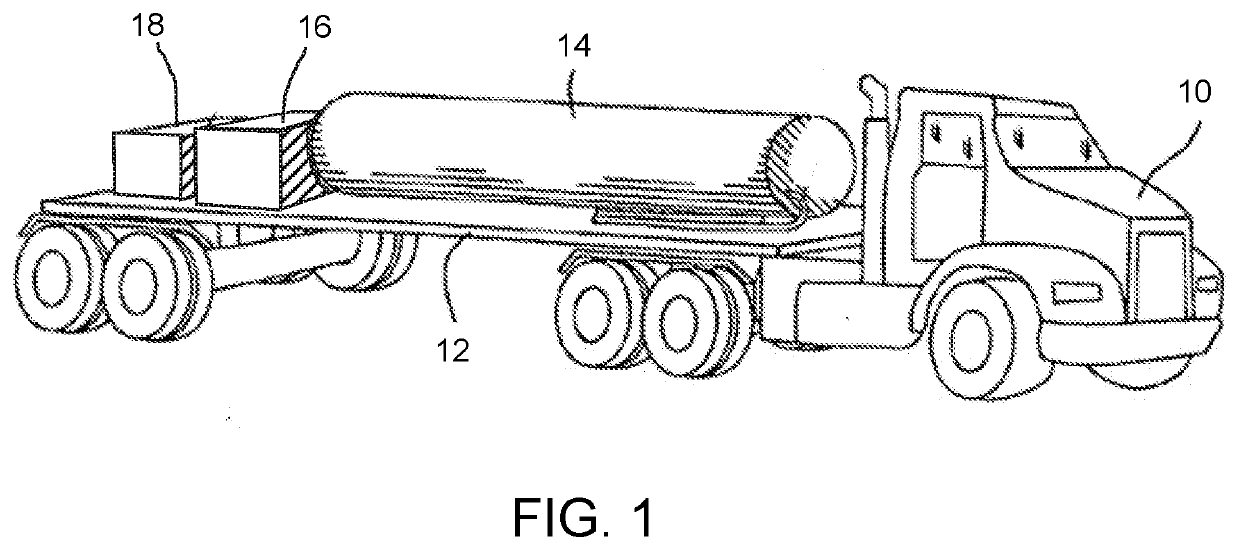
[0016]Natural gas may be transported by pipeline from the gas fields where it is produced to a liquefaction facility. The operators of liquefaction plants may desire to ensure that the LNG has a consistent composition and combustion characteristics. LNG plants achieve the desired LNG properties by cooling and condensing the natural gas. Once liquefied, the LNG can be loaded into tanks for delivery to the end use.
[0017]The processes for removing undesired components from natural gas to obtain gas that is acceptable for liquefaction are performed in preparation trains. Preparation trains may remove the following components prior to liquefaction: components that would freeze at cryogenic process temperatures during liquefaction, including carbon dioxide (CO2), water and heavy hydrocarbons, components that must be removed to meet the LNG product specifications, including hydrogen Sulfide (H2S), corrosive and erosive components such as mercury, inert components such as helium and nitrogen, and oil. A typical specification of gas for liquefaction may require less than 1 ppm of water, less than 100 ppm CO2, and less than 4 ppm H2S.
[0018]After the natural gas feedstock has been prepared for liquefaction, it may be fed into a liquefaction module. In the liquefaction module, the natural gas is cooled to −240° to −260° F. (−151° C. to −162° C.), at which temperature the vapor pressure is close to 1 atm (101 kPa). Liquefaction systems entail sequentially passing the gas at an elevated pressure through a plurality of cooling stages in which the gas is cooled to successively lower temperatures until the liquefaction temperature is reached. Cooling is generally accomplished by indirect heat exchange with one or more refrigerants such as propane, propylene, ethane, ethylene, methane, nitrogen, carbon dioxide, or combinations of the preceding refrigerants.
[0019]The liquefaction process may remove all non-hydrocarbon contaminates (CO2, dirt, oil, water) from the natural gas, providing an ultraclean form of gas. In some instances, C2+ hydrocarbons that condense during the liquefaction process are allowed to remain in the LNG product. In other instances, and typically in commercial LNG processes in the United States, C2+ hydrocarbons are removed during the liquefaction process, so that the resulting LNG typically includes at least 95% methane and more typically includes at least about 98% methane. Either form of LNG may be used in the present process and the term LNG is used herein to refer to either.
[0020]Referring now to FIG. 2, the resulting LNG may be used to enhance production according to the following steps.
[0021]In some embodiments, the LNG may be placed in a reusable storage tank. The tank may be used to transport the LNG to a desired usage location. In some cases, the LNG may be transported to a hydrocarbon production site, also referred to as a wellsite. The transport of LNG to the well may be carried out using a transport vehicle such as a truck. The transport vehicle may also transport a regasifier, vaporizer, and/or compressor to the well. The tank, regasifier, vaporizer, and/or compressor may form a system that may be transported from one well to another, providing LNG for injection at each well as-needed. By way of example, the LNG tank truck that delivers LNG to the wellsite may include a trailer on which regasification equipment is mounted. By way of example only and as illustrated in the Figure, a tractor 10 and trailer 12 may transport an LNG tank 14, a regasifier 16, and a compressor 18 to a well that is to be treated and from one well to another.
[0022]In some instances, storage and transportation of LNG may be governed by regulations, including but not limited to, in the United States, 49 C.F.R. §§ 193 and 178 and in particular, Specification MC-338, which governs insulated cargo tank motor vehicles. In such instances, equipment and personnel qualifications may be specified.
[0023]Once at the wellsite, the LNG may be fed to a vaporizer and then to a compressor, which may or may not be on a transport vehicle as shown in the drawing. Alternatively, the LNG may be sent to a high-pressure pump and then to a vaporizer. In either case, the output may comprise gas at a pressure slightly above the well casing pressure, which may be 150 to 4500 psig (1,030 to 31,025 kPa) and at a temperature in the range of 150 to 200° F. (65 to 95° C.). In some embodiments, the output pressure may be about 10% higher than the formation pressure. Heat for regasifying (vaporizing) the LNG may be provided from any suitable source, including but not limited to, ambient air, combustion of gas or other fuel, electric heating, or any other heat source.
[0024]The resulting gas stream comprising pressurized regasified LNG may be injected into a desired subsurface formation via one or more injection wells. Injection may be at a desired rate and make take place over a period time. In some instances, injection may be performed so as to inject a desired volume of regasified gas.
[0025]As mentioned above, an LNG tanker (vehicle) may include regasification equipment. Because the rate at which the regasified LNG is injected is relatively low, the regasification equipment can be sized accordingly. In other instances, a regasification plant may be installed permanently or semi-permanently at a wellsite.
[0026]The regasified LNG may have a water content of less than about 5 PPM and in some instances less than about 1 PPM. It has been discovered that this dry unsaturated gas has the ability to take up other hydrocarbons and is effective for enhancing production. Wells into which regasified LNG has been injected have seen production rise dramatically, in some cases as much as 20% or more. In some instances, production begins to increase within 24 hours.
[0027]By way of example only, regasified LNG was injected into a well that had been producing less than one barrel per hour of oil. The regasified LNG was injected at a rate of 18000 SCFH for 24 hours, after which production was resumed. Without additional intervention, production of oil from the well rose to 43 barrels/day following the LNG injection.
[0028]The following table gives production data for an exemplary well in which well enhancement using injected LNG began on Day 3. As can be seen, production increased rapidly and significantly.
Oil Prod Gas Prod Day # (barrels) (barrels) 1 0 0 2 0 0 3 0 0 4 8.73 8.13 5 39.53 36.71 6 43.63 37.11 7 41.42 40.86 8 38.09 38.97 9 40.74 45.6 10 36.17 40.88 11 36.57 33.94 12 40.37 43.77 13 42.64 42.78 14 40.37 42.3 15 39.1 39.2 16 38.65 35.48 17 40.04 40.54 18 43.39 38 19 39.2 35.85 20 37.25 38.41
[0029]Once it has returned to the surface, the pressurized, regasified natural gas that was injected into the well can be separated from the produced liquids and sent to a gas production line for transmission to a gas processing facility, instead of to a flare or vent stack. Because LNG is cleaner than produced gas, in some instances, the lift gas returning to the surface may be fed directly into production lines with only minimal standard processing and, in some embodiments, without undergoing gas separation. Likewise, since LNG is cleaner than pipeline gas, the gas returning to the surface often requires no further processing for sales. In some embodiments, the standard processing may include separation of produced gases from produced liquids, such as by passage through one or more vapor-liquid separators such as a flash drum, breakpot, knock-out drum or knock-out pot, compressor suction drum or compressor inlet drum.
[0030]Because of its compressed nature, a large amount of gas for use in the present method can be delivered to a well as LNG. Thus, the present process can operate for an extended period of time, unmanned, without violating emission regulations or permits. Similarly, the equipment required to operate the present process is more compact and can operate on well sites whose size or location restrict access by traditional methods. Well gases including CO2, NGLs and methane are all greenhouse gases. Because storage and/or cleanup may be impractical in some instances, gas that does not meet the pipeline specification may need to be flared. Traditional processes may cause these to be emitted to atmosphere, which can violate air permits. The present process reduces undesired emissions to nearly zero.
[0031]In other embodiments, the LNG can be injected into the well without regasification. If injected as a cryogenic fluid, the LNG may fracture the formation as it warms, thereby opening new fluid flow paths. As the injected fluid warms and flows through the formation, a front of liquid natural gas may form near the wellbore. In some cases, it may be desired to produce hydrocarbons and recover injected fluids from one or more adjacent wells that are fluidly connected to the injection well via the producing formation. In some cases, it may be desired to inject fluids for a period of time and then to cease injecting and produce hydrocarbons and recover injected fluids from the same well or wells that were used to inject the fluids.
[0032]The foregoing outlines features of several embodiments so that a person of ordinary skill in the art may better understand the aspects of the present disclosure. Such features may be replaced by any one of numerous equivalent alternatives, only some of which are disclosed herein. Likewise, unless expressly stated, the sequential recitation of steps in the claims that follow is not intended as a requirement that the steps be performed in the sequence recited.
[0033]One of ordinary skill in the art should appreciate that they may readily use the present disclosure as a basis for designing or modifying other processes and structures for carrying out the same purposes and/or achieving the same advantages of the embodiments introduced herein. One of ordinary skill in the art should also realize that such equivalent constructions do not depart from the spirit and scope of the present disclosure and that they may make various changes, substitutions, and alterations herein without departing from the spirit and scope of the present disclosure.

PUM

no PUM

Description & Claims & Application Information

We can also present the details of the Description, Claims and Application information to help users get a comprehensive understanding of the technical details of the patent, such as background art, summary of invention, brief description of drawings, description of embodiments, and other original content. On the other hand, users can also determine the specific scope of protection of the technology through the list of claims; as well as understand the changes in the life cycle of the technology with the presentation of the patent timeline. Login to view more.

Similar technology patents

Ophthalmic composition with a viscosity enhancement system having two different viscosity enhancing agents

InactiveUS20120269862A1lower viscosityenhance viscosity
Owner:ALCON RES LTD

Co-surfactant foam-forming composition for enhanced oil recovery

ActiveUS20180037809A1lower viscosity
Owner:DOW GLOBAL TECH LLC +1

Processing of oil by steam addition

ActiveUS10294429B1reduce energy consumptionlower viscosity
Owner:PHILLIPS 66 CO

High Performing Low Viscosity Tire Sealant

ActiveUS20210238394A1high performancelower viscosity
Owner:ILLINOIS TOOL WORKS INC

Classification and recommendation of technical efficacy words

  • lower viscosity
  • increased pressure

Two-solder method for self-aligning solder bumps in semiconductor assembly

InactiveUS20130228916A1reduce viscous solder damplower viscosity
Owner:TEXAS INSTR INC

Composite electrode material

ActiveUS20110068294A1lower viscosity
Owner:HYDRO QUEBEC CORP +1

Lubricating Oil Composition For Automoblie Engine Lubrication.

InactiveUS20130237465A1lower viscosityimprove fuel efficiency
Owner:CHEVRON JAPAN

Glass composition for sealing

ActiveUS20160236967A1lower viscosity
Owner:NIHON YAMAMURA GLASS

Systems and methods for power generation with exhaust gas recirculation

ActiveUS20080309087A1reduce nox emmissionincreased pressure
Owner:GENERAL ELECTRIC CO

Pressure-based fluid flow sensor

InactiveUS7647842B1increase deflectionincreased pressure
Owner:HONEYWELL INT INC
Why Eureka
Try Eureka