This helps you quickly interpret patents by identifying the three key elements:
Problems solved by technology
Method used
Benefits of technology
Benefits of technology
The present invention relates to a liquid jetting head and an ink-jet printer. The technical effect of this invention is to prevent the transmission of heat from warmed ink to the joining portion of the wiring member and channel substrate, which can lead to an internal stress and detachment of the wiring member from the channel substrate. This is achieved by designing a liquid jetting head with a cavity between the pressure chambers and the connecting points of the wirings and terminals, which reduces the risk of thermal expansion and ensures stable connection between the wiring member and the channel substrate. Additionally, the invention includes an ink supply unit and a heater to further improve the performance of the liquid jetting head.
Problems solved by technology
Therefore, there is a risk that when heat of the warmed ink is transmitted to the joining portion of the wiring member and the channel substrate, an internal stress is generated between the adhesive of the wiring member and the individual electrode terminals and common electrode terminal, and the wiring member is detached from the channel substrate.
Method used
Image
Click on the blue label to locate the original text in one second.
Reading with bidirectional positioning of images and text.
Examples
first embodiment
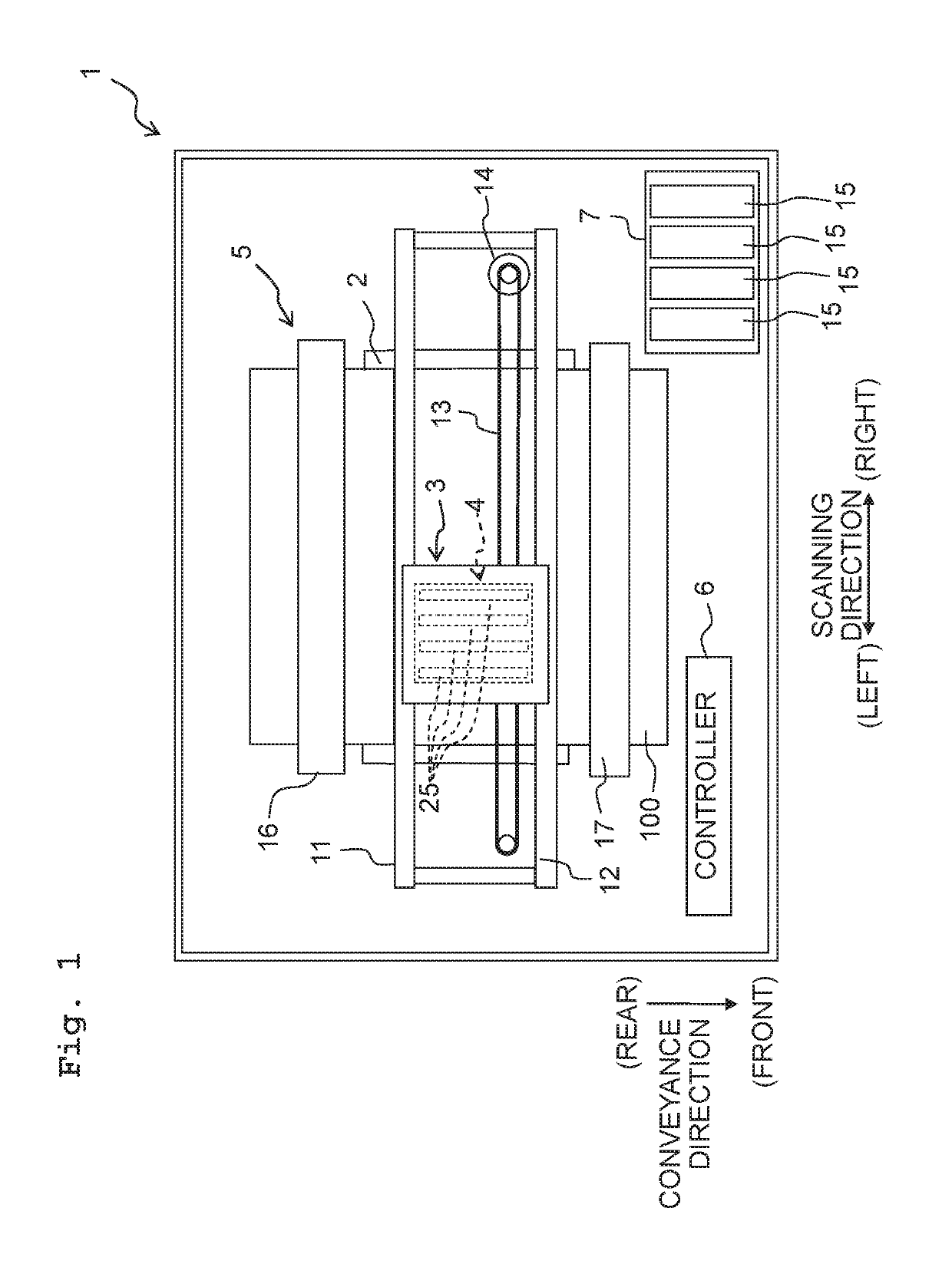
[0016]A first embodiment of the present teaching will be described. First, a schematic configuration of an ink-jet printer 1 will be described with reference to FIG. 1. Note that each of directions of front, rear, left, and right depicted in FIG. 1 are defined as “front”, “rear”, “left”, and “right” of the printer. Moreover, this side of the paper surface is defined as “up”, and the far side of the paper surface is defined as “down”. Hereafter, description will proceed making appropriate use of words for each of the directions of front, rear, left, right, up, and down.
[0017]
[0018]As depicted in FIG. 1, the ink-jet printer 1 mainly includes a platen 2, a carriage 3, an ink-jet head 4, a conveyance mechanism 5, and a controller 6.
[0019]A recording sheet 100 as a recording medium is placed on an upper surface of the platen 2. The carriage 3 is configured to reciprocate in a left-right direction (hereafter, also referred to a scanning direction) along two guide rails 11, 12 in a region ...
second embodiment
[0052]Next, a second embodiment of the present teaching will be described. A head unit 125 according to the second embodiment has a first channel substrate 136 and a second channel substrate 137 that differ from the first channel substrate 36 and the second channel substrate 37 of the head unit 25 according to the first embodiment. Therefore, the first channel substrate 136 and the second channel substrate 137 will be described below. Note that where something has a configuration similar to in the first embodiment, it will be described assigned with the same symbol as in the first embodiment.
[0053]In the present embodiment, as depicted in FIGS. 6 and 7B, two slits 149a each extending in the conveyance direction are formed between the two rows of pressure chambers 41, of the first channel substrate 136. The two slits 149a each penetrate the first channel substrate 136 in the up-down direction. In other words, a depth of each of the slits 149a is about 70 μm, the same as the thickness...
PUM
Abstract
A liquid jetting head includes: a nozzle plate having a nozzle surface in which nozzles are open; a channel member having a first surface and a second surface on an opposite side to the first surface, the nozzle plate being joined to the first surface, the channel member being formed with channels communicating with the nozzles respectively and a cavity being different from the channels, the channels including pressure chambers respectively; drive elements provided on the second surface of the channel member to correspond to the pressure chambers respectively, the drive elements having terminals led out to the second surface of the channel member; and a wiring member having wirings, the wirings being joined to the terminals respectively on the second surface of the channel member.
Description
CROSS REFERENCE TO RELATED APPLICATION[0001]The present application claims priority from Japanese Patent Application No. 2018-056902 filed on Mar. 23, 2018, the disclosure of which is incorporated herein by reference in its entirety.BACKGROUNDField of the Invention[0002]The present invention relates to a liquid jetting head and an ink-jet printer including the liquid jetting head.Description of the Related Art[0003]From the past, there is known a liquid jetting head that includes: a channel substrate having liquid channels formed therein; piezoelectric elements provided to the channel substrate to correspond to the liquid channels; and a wiring member equipped with a driver IC. The driver IC outputs a drive signal for driving each of the piezoelectric elements. A conventional liquid jetting head includes: individual electrodes that are individually provided to the piezoelectric elements; and a common electrode provided commonly to the piezoelectric elements. The respective individua...
Claims
Application Information
Patent Timeline
Application Date:The date an application was filed.
Publication Date:The date a patent or application was officially published.
First Publication Date:The earliest publication date of a patent with the same application number.
Issue Date:Publication date of the patent grant document.
PCT Entry Date:The Entry date of PCT National Phase.
Estimated Expiry Date:The statutory expiry date of a patent right according to the Patent Law, and it is the longest term of protection that the patent right can achieve without the termination of the patent right due to other reasons(Term extension factor has been taken into account ).
Invalid Date:Actual expiry date is based on effective date or publication date of legal transaction data of invalid patent.

