
Display panel and display device

A display panel, one-to-one correspondence technology, applied in the direction of organic semiconductor devices, electrical components, diodes, etc., can solve the problems of inconsistent center and edge thickness of color resist materials, viewing angle brightness attenuation, etc., to reduce viewing angle deviation and improve brightness attenuation. Effect

Active Publication Date: 2021-04-30
HUBEI YANGTZE IND INNOVAION CENT OF ADVANCED DISPLAY CO LTD
View PDF9 Cites 5 Cited by
  • Summary
  • Abstract
  • Description
  • Claims
  • Application Information

AI Technical Summary

Problems solved by technology

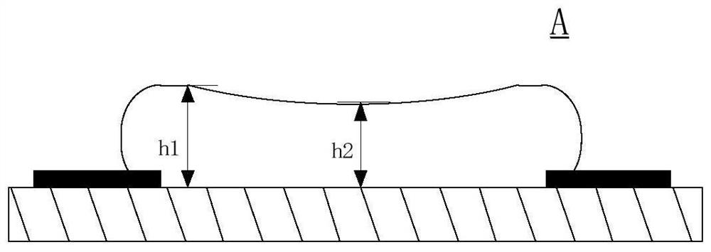
However, in the existing method of preparing a color filter on a display panel, a black matrix (Black matrix, BM) is made first, and then a color-resist layer is coated with a color-resist material. In this process, due to the existence of the black matrix, the color The resist material is accumulated at the overlapping position of the black matrix, so that the thickness of the center and edge of the color resist material is inconsistent, which leads to the problem of attenuation of viewing angle brightness

Method used


Image

  • Display panel and display device
  • Display panel and display device
  • Display panel and display device

Examples


Embodiment Construction

[0043] In order to make the above objects, features and advantages of the present invention more comprehensible, the present invention will be further described below in conjunction with the accompanying drawings and embodiments.

[0044] It should be noted that in the following description, specific details are set forth in order to fully understand the present invention. However, the present invention can be implemented in many other ways than those described here, and those skilled in the art can make similar extensions without departing from the connotation of the present invention. Accordingly, the present invention is not limited to the specific embodiments disclosed below. Also, in the following description, the same reference numerals denote the same or similar structures in the drawings, and thus their repeated descriptions will be omitted.

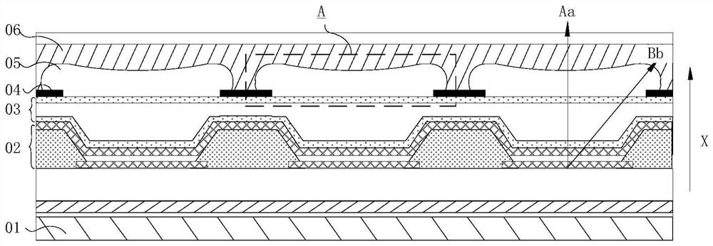
[0045] figure 1 is a schematic cross-sectional view of a display panel in the prior art, figure 2 for figure 1 Partial enl...


PUM

PropertyMeasurementUnit
particle diameteraaaaaaaaaa
refractive indexaaaaaaaaaa

Abstract

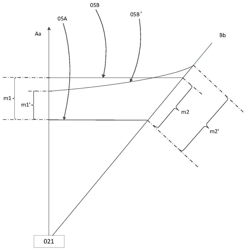
The invention describes a display panel and a display device. The display panel comprises a light-emitting device layer located at one side of a substrate, and a color resistance layer, wherein the color resistance layer is located on the side, away from the substrate, of the light-emitting device layer, the color resistance layer includes color resistance units arranged in an array mode, each color resistance unit includes a first part and a second part, and the projection of the second part on the substrate is located on the outer side of the projection of the first part on the substrate; the projection of the first part on the light-emitting device layer is located in a pixel opening; and the thickness of the first part in the first direction in at least parts of the color resistance units is not less than the thickness of the second part in the first direction. By arranging an auxiliary layer between at least parts of the color resistance units and a shading layer, the center thickness of the color resistance units can be more easily and controllably adjusted to be larger than or equal to the edge thickness of the color resistance units, and therefore large-view-angle brightness attenuation is improved, and view angle color cast of the display panel is reduced.

Description

technical field [0001] The present invention relates to the field of display technology, in particular to a display panel and a display device. Background technique [0002] Organic Light Emission Diode (OLED) display, as a new generation of display device, has the advantages of thin and light, high contrast, fast response, wide viewing angle, high brightness, full color, etc. Assistants (PDAs), digital cameras, vehicle displays, notebook computers, wall-mounted TVs, and military fields have very broad application prospects. [0003] In order to reduce the reflectivity of external light in the OLED display, a color filter is generally installed on the light emitting surface of the OLED display. This setting is better enough to reduce the reflection of ambient light in the OLED display. , improving the light emitting effect of the organic light emitting diode display. [0004] In the prior art, the color filter is integrated into the display panel, which not only improves t...

Claims


Application Information

Patent Timeline
Patent Type & Authority Applications(China)
IPC IPC(8): H01L51/52H01L27/32
CPCH10K59/8792H10K59/879H10K59/877H10K59/38H10K2102/351H10K50/858H10K50/854
Inventor 肖艾
Owner HUBEI YANGTZE IND INNOVAION CENT OF ADVANCED DISPLAY CO LTD
Learn More