Electric power cabinet convenient for discharging accumulated water

A power cabinet, a convenient technology, applied in electrical components, substation/distribution device casing, substation/switch layout details, etc., can solve the problem of affecting residential electricity communication, power cabinets are prone to water accumulation, and shorten the service life of power cabinets and other problems to achieve the effect of improving service life, avoiding short circuit phenomenon and avoiding water accumulation

Pending Publication Date: 2021-04-30
蒯苍帝
View PDF5 Cites 0 Cited by
  • Summary
  • Abstract
  • Description
  • Claims
  • Application Information

AI Technical Summary

Problems solved by technology

[0005] The purpose of the present invention is to solve the problem in the prior art that "in the process of using the existing power cabinet, it often encounters rainy weather, which will easily cause water accumulation inside the power cabinet, and excessive water accumulation will lead to power failure. The circuit wiring board inside the cabinet has a short circuit phenomenon, which directly affects the electricity communication of the residents in the community, and also shortens the service life of the electric cabinet", thus proposing a power cabinet that is convenient for discharging accumulated water

Method used


Image

  • Electric power cabinet convenient for discharging accumulated water
  • Electric power cabinet convenient for discharging accumulated water
  • Electric power cabinet convenient for discharging accumulated water

Examples


Embodiment Construction

[0021] The following will clearly and completely describe the technical solutions in the embodiments of the present invention with reference to the accompanying drawings in the embodiments of the present invention. Obviously, the described embodiments are only some, not all, embodiments of the present invention.

[0022] In describing the present invention, it should be understood that the terms "upper", "lower", "front", "rear", "left", "right", "top", "bottom", "inner", " The orientation or positional relationship indicated by "outside", etc. is based on the orientation or positional relationship shown in the drawings, and is only for the convenience of describing the present invention and simplifying the description, rather than indicating or implying that the referred device or element must have a specific orientation, so as to Specific orientation configurations and operations, therefore, are not to be construed as limitations on the invention.

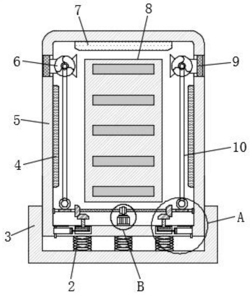
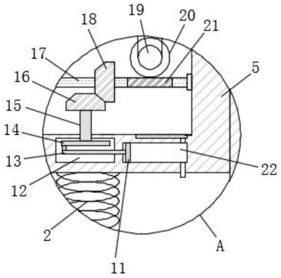
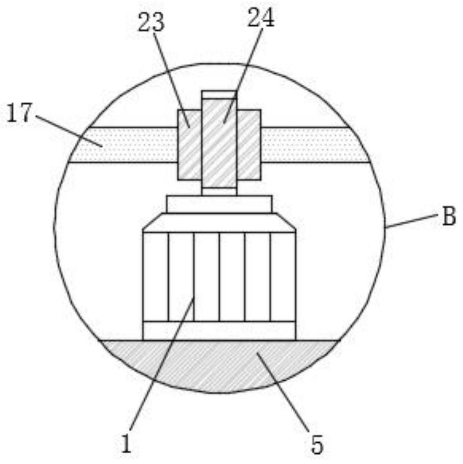
[0023] refer to Figure ...


PUM


Abstract

The invention discloses an electric power cabinet convenient for discharging accumulated water, the electric power cabinet comprises a drainage base and a cabinet body, the cabinet body is slidably connected in the drainage base, a mounting plate is fixedly mounted on the inner wall of the cabinet body, a transverse shaft is transversely and rotatably connected to the side wall in the cabinet body, and two second helical gears are symmetrically and fixedly connected to the transverse shaft. The lower end of each second bevel gear is connected with a first bevel gear in a meshed mode, a rotating shaft is fixedly installed in the center of the lower end of each first bevel gear, the lower end of each rotating shaft is rotatably connected to the side wall of the bottom end in the cabinet body, and two first sealing cavities are symmetrically formed in the side wall of the bottom end in the cabinet body. According to the invention, the drying degree in the cabinet body is improved, the phenomenon of water accumulation in the cabinet body is avoided, the short circuit phenomenon of the circuit wiring board in the cabinet body is further avoided, the influence on the power utilization communication of residents in a community is avoided, and the service life of the cabinet body is prolonged.

Description

technical field [0001] The invention relates to the technical field of power cabinets, in particular to a power cabinet that is convenient for draining accumulated water. Background technique [0002] Power cabinets (boxes) are divided into power power cabinets (boxes), lighting power cabinets (boxes), and metering cabinets (boxes), which are the final equipment of the power distribution system. The power cabinet is a general term for the motor control center. The power cabinet is used in the occasions where the load is relatively scattered and there are few circuits; the motor control center is used in the occasions where the load is concentrated and there are many circuits. They distribute the electric energy of a certain circuit of the upper-level power distribution equipment to the nearest load. This level of equipment shall provide protection, monitoring and control of the load. The installation requirements of the power cabinet are: the distribution board (box) shou...

Claims


Application Information

Patent Timeline
Patent Type & Authority Applications(China)
IPC IPC(8): H02B1/28H02B1/30H02B1/56H02B1/32
CPCH02B1/28H02B1/30H02B1/565H02B1/32
Inventor 蒯苍帝
Owner 蒯苍帝
Why Eureka
Try Eureka