Steel plate surface painting equipment for metal processing

A technology for metal processing, steel plate

Pending Publication Date: 2021-05-04
周成建
View PDF1 Cites 1 Cited by
  • Summary
  • Abstract
  • Description
  • Claims
  • Application Information

AI Technical Summary

Problems solved by technology

[0005] In order to overcome the shortcomings of traditional painting equipment that can’t evenly discharge materials, can’t realize automatic painting and automatic stirring and painting, the technical problem is: to provide a steel plate for metal processing that can be uniformly discharged and realize automatic painting and automatic stirring and painting Surface painting equipment

Method used


Image

  • Steel plate surface painting equipment for metal processing
  • Steel plate surface painting equipment for metal processing
  • Steel plate surface painting equipment for metal processing

Examples


Embodiment 1

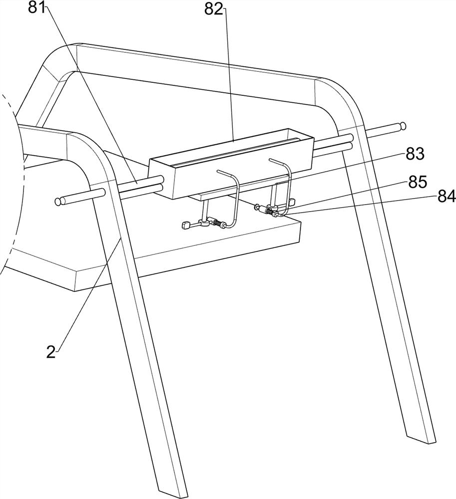
[0067] A steel plate surface painting equipment for metal processing, such as figure 1 As shown, it includes a first fixed plate 1, a track 2, a collection box 3, a clamping mechanism 4 and a blanking mechanism 5, the left and right sides of the first fixed plate 1 are provided with tracks 2, and the upper middle part of the first fixed plate 1 A collection box 3 is provided, a clamping mechanism 4 is provided on the upper part of the collection box 3, and a feeding mechanism 5 is provided on the first fixed plate 1 .

[0068] When people want to paint the steel plate, they can use this steel plate surface painting equipment for metal processing. First, the user places the steel plate in the clamping mechanism 4, and the steel plate is clamped by the clamping mechanism 4. The user then pours the paint into the blanking mechanism 5, so that the paint is sprayed out through the blanking mechanism 5, and the user moves the blanking mechanism 5 backwards, and the blanking mechanis...

Embodiment 2

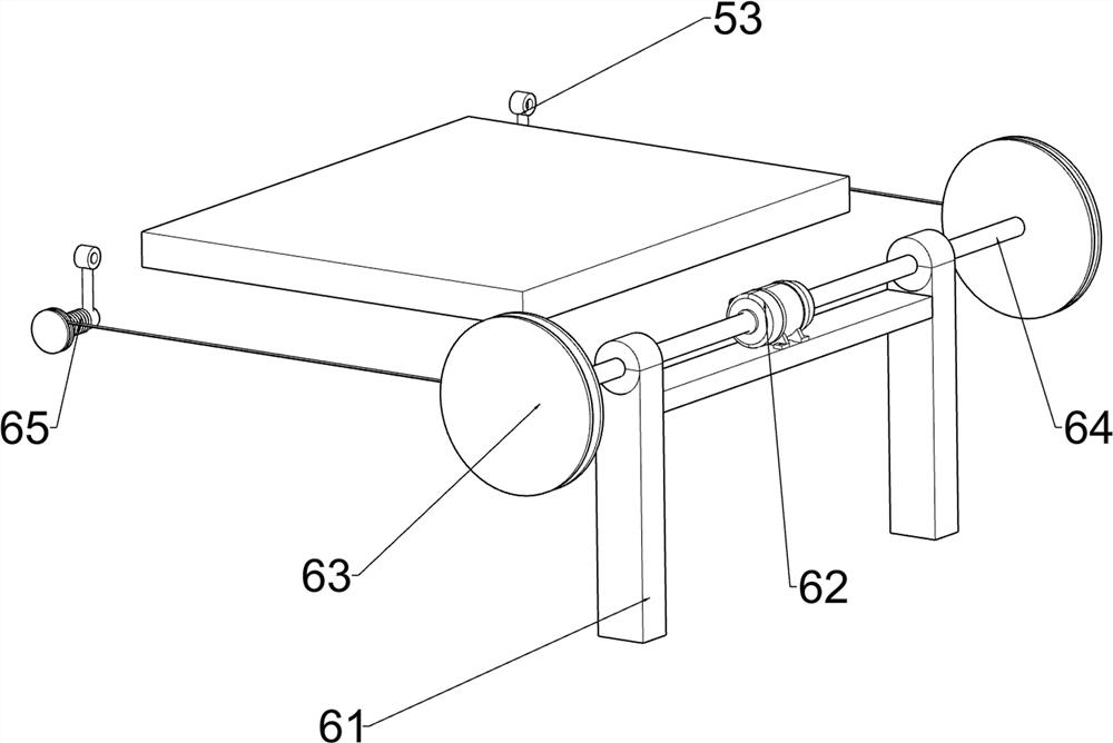
[0070] On the basis of Example 1, such as figure 2 and image 3 As shown, the clamping mechanism 4 includes a first U-shaped bar 41, a clamping block 42, a first bar 43 and a first spring 44, and four first U-shaped bars 41 are arranged on the top of the collection box 3, and the same side A first rod 43 is provided between the two first U-shaped rods 41, and a clamping block 42 is slidably connected between the two first rods 43. The number of clamping blocks 42 is two, and the two first A first spring 44 is wound around each rod member 43 , and both ends of the first spring 44 are connected to the clamping block 42 .

[0071] The user pushes the two clamping blocks 42 in reverse, so that the two clamping blocks 42 move in the opposite direction, the first spring 44 stretches, and the two clamping blocks 42 are separated from each other, and the user places the steel plate between the two clamping blocks. Between the blocks 42, the clamping block 42 is loosened, and the fi...

Embodiment 3

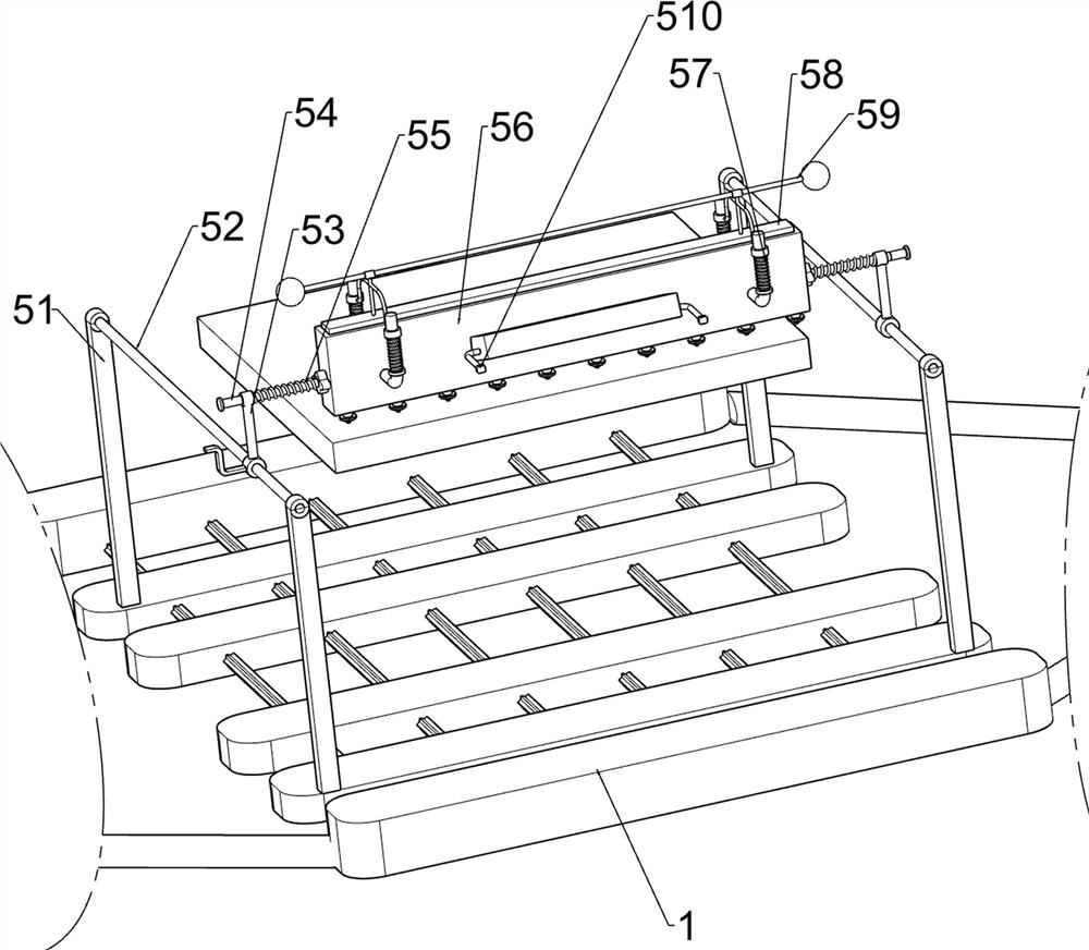
[0075] On the basis of Example 2, such as Figure 4-Figure 7 As shown, a pulling mechanism 6 is also included, the upper and rear side of the first fixed plate 1 is provided with a pulling mechanism 6, and the pulling mechanism 6 includes a second support rod 61, a motor 62, a reel assembly 63, a first rotating shaft 64 and a second Four springs 65, the rear side on the first fixed plate 1 is provided with a second support rod 61, a motor 62 is installed in the middle of the second support rod 61 tops, and the output shafts of the two motors 62 are connected with the first rotating shaft 64, the first rotating shaft 64 It is rotatably connected with the second support rod 61, and a reel assembly 63 is connected between the first sliding sleeve 53 and the first rotating shaft 64. There are two reel assemblies 63, and the reel assembly 63 and the first sliding sleeve 53 is connected with a fourth spring 65, and the number of the fourth spring 65 is two.

[0076] The user starts...


PUM


Abstract

The invention relates to painting equipment, in particular to steel plate surface painting equipment for metal processing. According to the steel plate surface painting equipment for metal processing, discharging is uniform, and automatic painting and automatic stirring painting are achieved. The steel plate surface painting equipment for metal processing comprises a first fixing plate, a collecting box, a clamping mechanism and a discharging mechanism; rails are arranged at the left side and the right side of the first fixing plate; the collecting box is arranged at the upper middle part of the first fixing plate; the clamping mechanism is arranged at the upper part of the collecting box; and the discharging mechanism is arranged on the first fixing plate. According to the steel plate surface painting equipment, by loosening clamping blocks and resetting a first spring, the two clamping blocks are driven to move oppositely, the clamping blocks make contact with a steel plate, the steel plate is clamped by the clamping blocks, and the clamping effect is achieved.

Description

technical field [0001] The invention relates to a painting device, in particular to a painting device for the surface of a steel plate used for metal processing. Background technique [0002] Painting equipment is an important equipment in the surface manufacturing process. It is used to change the shortcomings of the material itself by spraying paint. It is mainly used to improve the appearance quality and performance of the material. However, dirt such as grease will adhere to the surface of the steel plate, resulting in the existing steel plate. When the painting equipment sprays paint on the steel plate, the paint cannot adhere to the surface of the steel plate. Not only that, but the existing steel plate spraying equipment is generally difficult to remove the rust on the steel plate surface, resulting in protrusions on the steel plate surface, which affects the appearance and performance of the steel plate . [0003] Patent application CN108787577A, the publication dat...

Claims


Application Information

Patent Timeline
IPC IPC(8): B05B16/20B05B13/02B24B7/10B24B41/02B24B41/04
CPCB05B13/02B24B7/10B24B41/02B24B41/04B05B16/20
Inventor 周成建
Owner 周成建
Why Eureka
Try Eureka