Welding device for high-end equipment manufacturing

A welding device and equipment technology, applied in auxiliary devices, manufacturing tools, welding equipment, etc., can solve problems such as poor fixation stability, inability to realize automatic splicing, and inability to automatically weld

Pending Publication Date: 2021-05-04
吴彬
View PDF1 Cites 4 Cited by
  • Summary
  • Abstract
  • Description
  • Claims
  • Application Information

AI Technical Summary

Problems solved by technology

[0005] In order to overcome the shortcomings of traditional welding, such as poor fixation stability, inability to realize automatic splicing and automatic welding, the techni

Method used


Image

  • Welding device for high-end equipment manufacturing
  • Welding device for high-end equipment manufacturing
  • Welding device for high-end equipment manufacturing

Examples


Embodiment 1

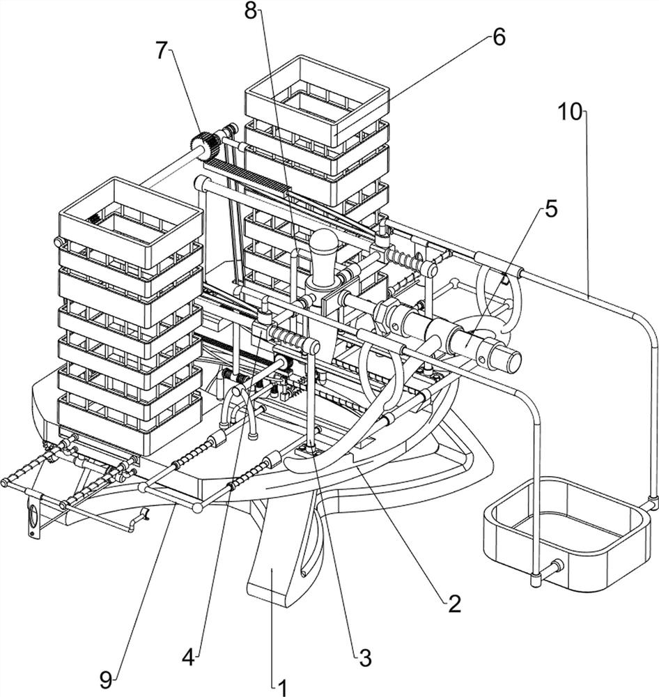
[0079] A welding device for high-end equipment manufacturing, such as figure 1 As shown, it includes a leg 1, a mounting plate 2, a first bracket 3, a welding mechanism 4 and a pushing mechanism 5, the leg 1 is provided with a mounting plate 2, and two first brackets 3 are provided on the left and right sides of the top of the mounting plate 2 A welding mechanism 4 is provided between the four first brackets 3 , and a pushing mechanism 5 is provided on the front side of the top of the mounting plate 2 .

[0080] When people want to weld metal plates, they can use this welding device for high-end equipment manufacturing. First, the user places two metal plates on the mounting plate 2 to splice the two metal plates together. The person starts the welding mechanism 4, and then starts the pushing mechanism 5, and the pushing mechanism 5 drives the welding mechanism 4 to move backward, so that the welding mechanism 4 contacts the two metal plates, and the welding mechanism 4 welds ...

Embodiment 2

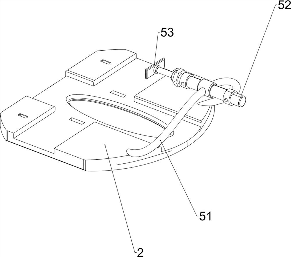
[0082] On the basis of Example 1, such as figure 2 with image 3 As shown, the welding mechanism 4 includes a first sliding rod 41, a first sliding sleeve 42, an electric welding torch 43 and a first spring 44, and the first sliding rod 41 is connected between the two first brackets 3 on the same side. A first sliding sleeve 42 is slidably connected between the first sliding rods 41, and the middle part of the first sliding sleeve 42 is provided with an electric welding torch 43, and a first spring 44 is wound on the two first sliding rods 41, and the first spring 44 The two ends are respectively connected with the first bracket 3 and the first sliding sleeve 42 on the front side.

[0083] The user splices the two metal plates on the mounting plate 2 together, starts the electric welding torch 43, and the user pushes the first sliding sleeve 42 backward, so that the first sliding sleeve 42 moves backward, thereby driving the electric welding torch 43 to move backward , the ...

Embodiment 3

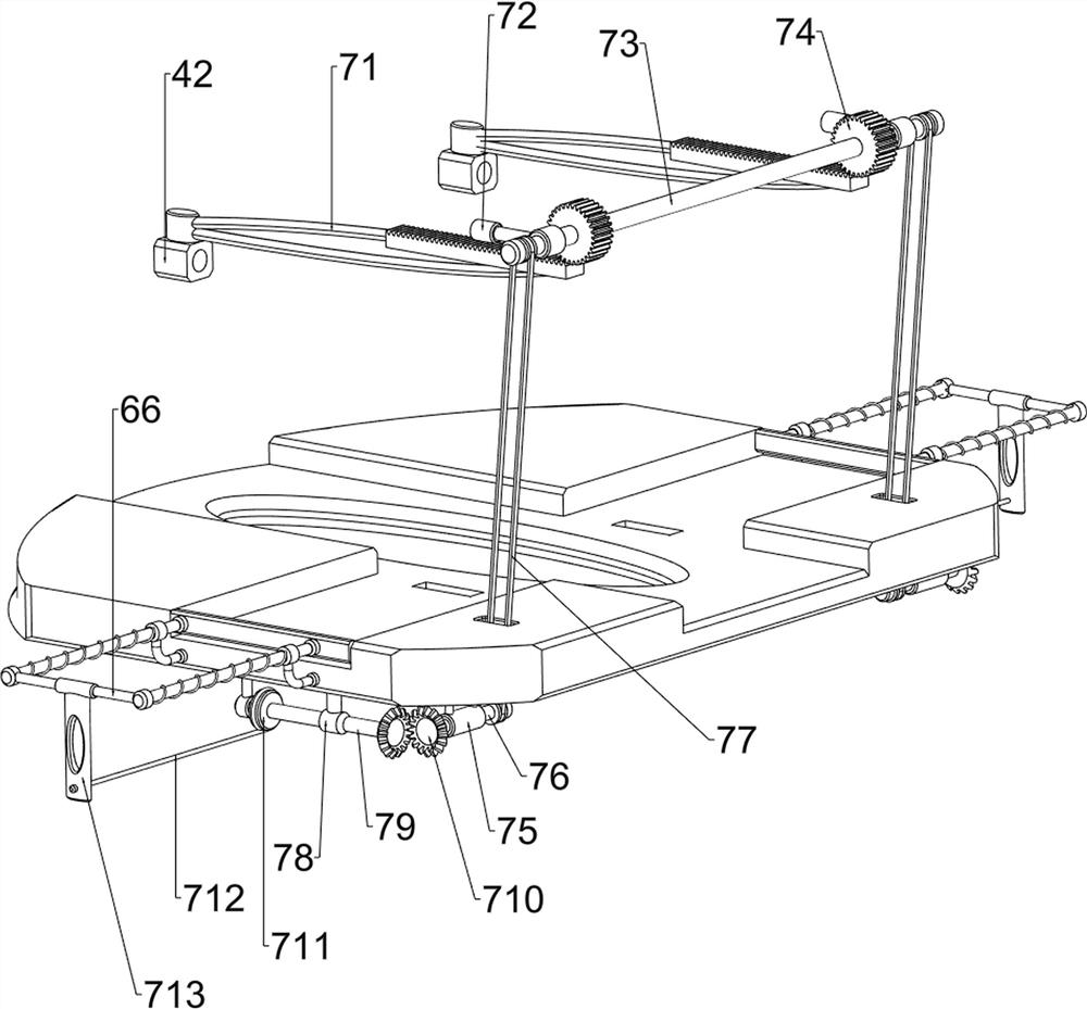
[0087] On the basis of Example 2, such as Figure 4-Figure 8 As shown, a blanking mechanism 6 is also included. The rear side of the mounting plate 2 is provided with a blanking mechanism 6. The blanking mechanism 6 includes a second sliding sleeve 61, a block 62, a second spring 63, a discharging frame 64, a second Three sliding sleeves 65, push blocks 66 and the third spring 67, the rear side of the bottom of the mounting plate 2 are all provided with a second sliding sleeve 61, and the two second sliding sleeves 61 are slidingly provided with a block 62, two blocks 62 are wound with two second springs 63, the two ends of the second spring 63 are respectively connected with the second sliding sleeve 61 and the block 62, the left and right parts of the rear side of the mounting plate 2 are provided with a discharge frame 64, and the mounting plate 2 Two third sliding sleeves 65 are provided on the left and right walls of the rear side, and push blocks 66 are slidably connecte...


PUM


Abstract

The invention relates to a welding device, in particular to a welding device for high-end equipment manufacturing. The welding device for high-end equipment manufacturing is higher in fixing stability and capable of achieving automatic splicing and automatic welding. The welding device for high-end equipment manufacturing comprises a supporting leg, first supports, a welding mechanism and a pushing mechanism, and a mounting plate is arranged on the supporting leg; each of the left side and the right side of the top of the mounting plate is provided with the two first supports. the welding mechanism is arranged among the four first supports; and the pushing mechanism is arranged on the front side of the top of the mounting plate. A first sliding sleeve is pushed backwards to move backwards, so that an electric welding gun is driven to move backwards, a first spring is stretched, and after the electric welding gun makes contact with two metal plates, the electric welding gun welds the two metal plates, and the welding effect is achieved.

Description

technical field [0001] The invention relates to a welding device, in particular to a welding device used in high-end equipment manufacturing. Background technique [0002] In the process of using metal plates, most of them need to be processed. The metal plates need to be spliced, welded, bent and other procedures. In the existing metal plate processing process, sometimes multiple people are needed to assist. Fix it or put it on the ground for processing. The stability of manual fixation is poor, it is easy to shake, which affects the processing effect, and may cause injury to the workers during the processing. If it is placed on the ground, the ground may be uneven, which will also affect the processing. effect, and can only be processed from one angle, workers are prone to fatigue and reduce work efficiency. [0003] Patent application CN208467629U, with a publication date of 20190205, discloses a new type of metal plate welding fixture, including mounting holes, extruded...

Claims


Application Information

Patent Timeline
IPC IPC(8): B23K37/00B23K37/02B23K37/04
CPCB23K37/00B23K37/0247B23K37/0408
Inventor 吴彬
Owner 吴彬
Why Eureka
Try Eureka