System for verifying and testing stray light resistance of star sensor

A star sensor and test system technology, which is applied in the field of aerospace star space detection, can solve problems that affect the accuracy of star sensor attitude measurement, the system cannot extract targets, and affect the system's detection or recognition capabilities.

Pending Publication Date: 2021-05-04
SHANGHAI AEROSPACE CONTROL TECH INST
View PDF6 Cites 0 Cited by
  • Summary
  • Abstract
  • Description
  • Claims
  • Application Information

AI Technical Summary

Problems solved by technology

The impact of stray light on the system, if it is mild, will reduce the signal-to-noise ratio and contrast of the target, thus affecting the detection or identification capabilities of the entire system; if it is severe, the detected target signal will be completely lost in the background of stray light, and the system cannot extract target; or due to the uneven distribution of stray light on the image plane, a false signal is formed on the system detector, causing the system to detect a false target or even cause the entire system to fail, seriously affecting the attitude measurement accuracy of the star sensor

Method used


Image

  • System for verifying and testing stray light resistance of star sensor
  • System for verifying and testing stray light resistance of star sensor
  • System for verifying and testing stray light resistance of star sensor

Examples


Embodiment 1

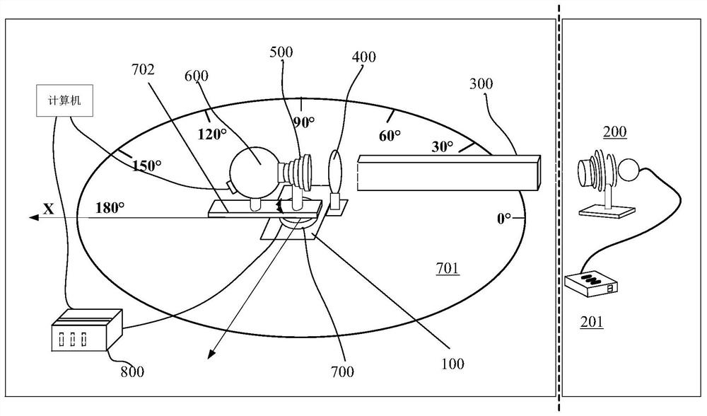
[0026] Such as figure 1 As shown, this embodiment provides a star sensor anti-stray light performance verification and testing system, including: an optical platform 100 .

[0027] a solar simulator 200, which is located at one end of the optical platform 100, and the solar simulator 200 is used to emit quasi-parallel radiation beams;

[0028] A beam shaping system 300, which is arranged near the exit of the solar simulator 200, the beam shaping system 300 is used to shape the radiated parallel irradiation beam to obtain Matching irradiance beam.

[0029] The optical chopper 400 is arranged at a position close to the exit of the beam shaping system, and the optical chopper is used to modulate and output the irradiation beam.

[0030] The mechanical movement device 700 is arranged on the optical table 100 and is arranged close to the optical chopper 400 .

[0031] The target to be measured is set on the mechanical movement device 700 , and the target to be measured is irradi...

Embodiment 2

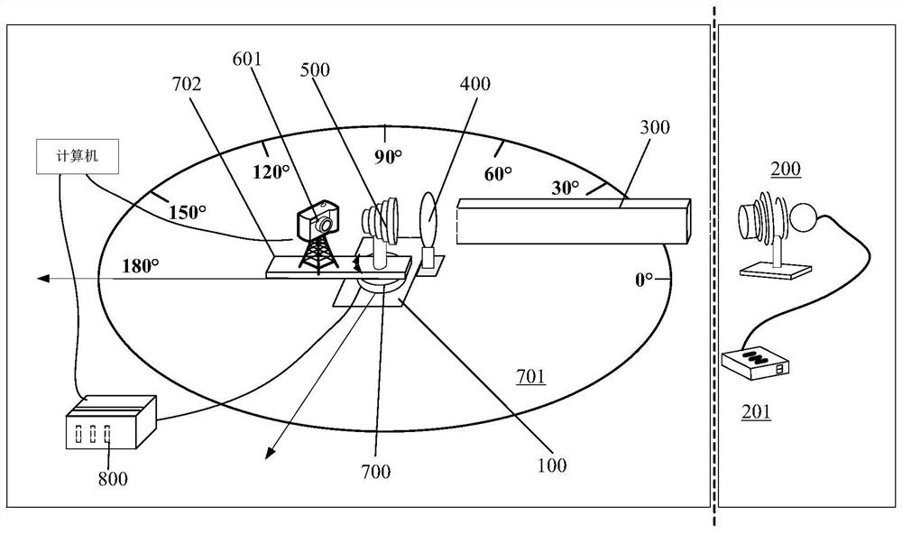
[0040] Such as figure 2 As shown, this embodiment provides a star sensor anti-stray light performance verification and testing system, including: an optical platform 100 .

[0041] A solar simulator 200 is located at one end of the optical platform 100, and the solar simulator 200 is used to emit quasi-parallel radiation beams.

[0042] A beam shaping system 300, which is arranged at a position close to the exit of the solar simulator 200, the beam shaping system 300 is used to shape the quasi-parallel irradiation beam to match the size of the light entrance of the target to be measured radiation beam.

[0043] An optical chopper 400 is arranged at a position close to the exit of the beam shaping system.

[0044] The optical chopper is used to modulate and output the irradiation beam.

[0045] The mechanical movement device 700 is arranged on the optical table 100 and is arranged close to the optical chopper 400 .

[0046] The target to be measured is set on the mechanica...

Embodiment 3

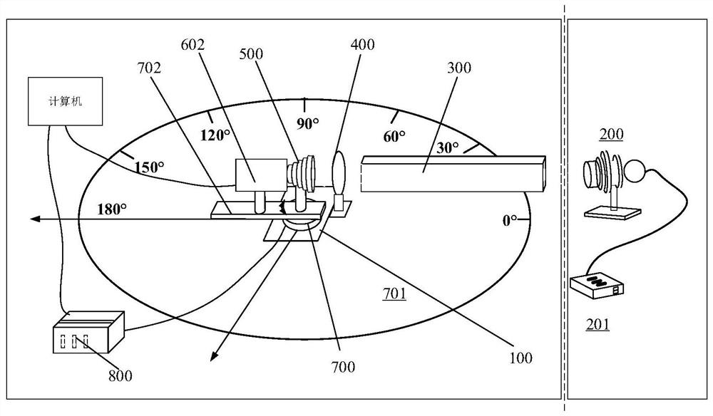
[0053] Such as image 3 As shown, this embodiment provides a star sensor anti-stray light performance verification and testing system, including: an optical platform 100 .

[0054] A solar simulator 200 is located at one end of the optical platform 100, and the solar simulator 200 is used to emit quasi-parallel radiation beams.

[0055] A beam shaping system 300, which is arranged at a position close to the exit of the solar simulator 200, the beam shaping system 300 is used to shape the quasi-parallel irradiation beam to match the size of the light entrance of the target to be measured radiation beam.

[0056] The optical chopper 400 is arranged at a position close to the exit of the beam shaping system, and the optical chopper is used to modulate and output the irradiation beam.

[0057] The mechanical movement device 700 is arranged on the optical platform 100 and is arranged close to the optical chopper 400 .

[0058] The target to be measured is set on the mechanical m...


PUM


Abstract

The invention discloses a system for verifying and testing the stray light resistance of a star sensor. The system comprises an optical platform, a solar simulator, a light beam shaping system, an optical chopper, a mechanical movement device and a to-be-measured target, wherein the solar simulator is located at one end of the optical platform, and the solar simulator is used for emitting quasi-parallel irradiation beams; the light beam shaping system is arranged at a position close to an outlet of the solar simulator and is used for aligning the parallel irradiation light beams to perform shaping so as to obtain the irradiation light beams matched with the size of the light inlet of the target to be detected; the optical chopper is arranged at the position close to an outlet of the light beam shaping system, and the optical chopper is used for modulating and outputting the irradiation light beam; the mechanical movement device is arranged on the optical platform and is close to the optical chopper; and the to-be-measured target is arranged on the mechanical movement device, and the to-be-measured target is irradiated by the modulated irradiation light beam so as to evaluate the stray light resistance of the to-be-measured target. According to the system, the stray light suppression level of the star sensor can be effectively evaluated, and a test and evaluation means is provided for in-orbit application of the star sensor.

Description

technical field [0001] The invention relates to the technical field of aerospace starry space detection, in particular to a star sensor anti-stray light performance verification and testing system. Background technique [0002] The star sensor is mainly aimed at imaging weak and small moving targets in space, and works in harsh environments with strong radiation sources (such as the sun, moon, and earth) outside the field of view of the system, and the background stray light has a serious impact. The impact of stray light on the system, if it is mild, will reduce the signal-to-noise ratio and contrast of the target, thus affecting the detection or identification capabilities of the entire system; if it is severe, the detected target signal will be completely lost in the background of stray light, and the system cannot extract or due to uneven distribution of stray light on the image plane, a false signal is formed on the system detector, causing the system to detect a false ...

Claims


Application Information

Patent Timeline
Patent Type & Authority Applications(China)
IPC IPC(8): G01C25/00
CPCG01C25/00
Inventor 高文杰杜伟峰张惠翟正一谢廷安叶宋杭武斌
Owner SHANGHAI AEROSPACE CONTROL TECH INST
Why Eureka
Try Eureka