Grounding switch static contact and straight swing plug-in grounding switch

A technology of grounding switch and static contact, which is applied in the direction of grounding switch, electric switch, air switch parts, etc., which can solve the problems of difficult design and manufacture, limited obstruction, etc., to ensure service life, reduce extra wear, and facilitate installation Effect

Active Publication Date: 2021-05-04
PINGGAO GRP +3
View PDF19 Cites 1 Cited by
  • Summary
  • Abstract
  • Description
  • Claims
  • Application Information

AI Technical Summary

Problems solved by technology

[0006] The purpose of the present invention is to provide a static contact of a grounding switch to solve the problem that in the prior art, buffer sheets are provided ...

Method used


Image

  • Grounding switch static contact and straight swing plug-in grounding switch
  • Grounding switch static contact and straight swing plug-in grounding switch
  • Grounding switch static contact and straight swing plug-in grounding switch

Examples


Embodiment 1

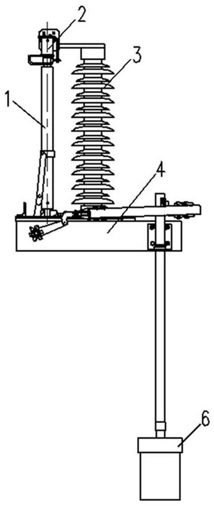
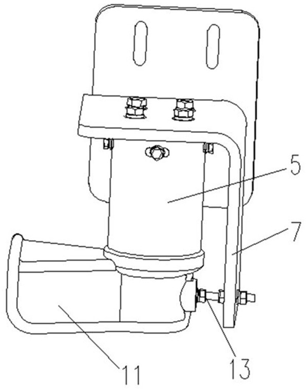
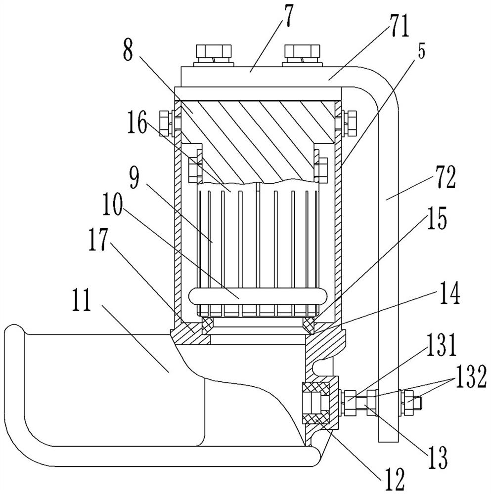
[0065]In the static contact head 2 of the ground switch provided by the present invention, an elastic buffer member 12 is disposed on the closed end of the guide channel, the elastic buffer member 12 being arranged in the guide channel, and the moving contact swing into the guide channel and moves to the guide channel. At the end, it will be equipped with the elastic buffer 12 elasticized, and the movable contact is slowed down and stopped. It is convenient for the next step inserting the upper tubular portion 5 to electrically conductive connection with the inside. The movable contact is buffered by the elastic buffer 12 positive to guide the guide channel, and the elastic buffer 12 of the appropriate elastic coefficient is selected, and the mounting is also convenient, and it is not easy to cause scratch wear, reducing the moving contact. The additional wear of the head is guaranteed to the life of the moving contact.

[0066]In this embodiment, the ground switch is a straight-grade ...

specific Embodiment 2

[0081]The difference from 1 of the examples is mainly in: in Example 1, the elastic buffer member is a rubber member. In the present embodiment, the elastic buffer member is a compressive spring, and the two-way spring of the bottom portion of the chassis is fixed to the closed end by the pressure plate, and the pressure plate is fixed to the closed end by fastening screw.

specific Embodiment 3

[0083]Its difference from the first embodiment is mainly in: in Example 1, the elastic buffer member is detachable in the groove by fastening bolt. In the present embodiment, the rubber member as an elastic buffer can also be tightly inserted in the groove, at this time, since the rubber member is often impacted, it will force it to press the recess, and the rubber member is not easy. Unexpected fallfield.


PUM


Abstract

The invention relates to a grounding switch static contact and a straight swing plug-in grounding switch, and the grounding switch static contact comprises an upper cylinder part which is internally provided with a static contact finger, and a lower guide cover fixedly arranged at the lower end of the upper cylinder part; one end of the guide channel is an open end, and the other end is a closed end; an elastic buffer piece is arranged at the closed end in a protruding mode, and the elastic buffer piece is arranged towards the guide channel and used for being in elastic jacking fit with a moving contact entering the guide channel in a swinging mode so that the moving contact can be buffered and decelerated. When the moving contact swings to enter the guide channel and moves to the end of the guide channel, the moving contact is elastically pressed and matched with the elastic buffer piece, and the elastic buffer piece buffers, decelerates and stops the moving contact, so that the moving contact is conveniently inserted into the upper cylinder part along a straight line in the next step, and is electrically connected with the static contact arranged inside. The moving contact is buffered by using the elastic buffer member facing the guide channel, so that the elastic buffer member with a proper elastic coefficient can be selected conveniently, and the installation is relatively convenient.

Description

Technical field[0001]The present invention belongs to the field of grounding switch, and more particularly to a ground-ground switching and straight insertion ground switch.Background technique[0002]High voltage AC grounding switch is a common switching device in the power system, mainly used for the reliable grounding of electrical equipment such as high-pressure bus bar, isolating switch, instead of carrying the ground line, reliably grounding high voltage equipment and lines, protecting personal property Safety. The ground portion is maintained when the circuit is maintained, which can carry short-circuit current under abnormal conditions, such as system short circuit currents.[0003]At present, the grounding switch generally uses a foldable or straight-grade, wherein the direct grounding switch structure is that the structure is simple, the fault rate is small, and the disadvantage is that the moving contact speed is fast, the contact and quiet The collision is more intense when ...

Claims


Application Information

Patent Timeline
IPC IPC(8): H01H31/02H01H31/00
CPCH01H31/023H01H31/003
Inventor 孙玉洲李竞王巧红郭海涛李付永朱全胜柴影辉夏立国赵子龙师丽芳钟荣松罗飞熊赵文杰李宇鹏周姝尹婷
Owner PINGGAO GRP
Why Eureka
Try Eureka