

Mounting structure and mounting method of motor shell
A technology of motor housing and installation structure, applied in the directions of electromechanical devices, housing/cover/support, electrical components, etc., can solve the problems of limited shock absorption, inconvenient installation, complicated installation, etc., and achieve simple and convenient installation. , Fast installation, and the effect of reducing the impact
- Summary
- Abstract
- Description
- Claims
- Application Information
AI Technical Summary
Problems solved by technology
Method used
Image

Examples
Embodiment 1
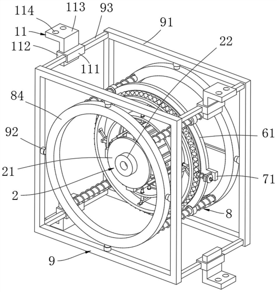
[0047] Example 1, please refer to Figure 1-10 , this embodiment provides a technical solution: an installation structure of a motor housing, including a motor housing 1, a front end cover unit 2, a rear end cover unit 3, a circumferential buffer unit 4, an axial buffer unit 5 and Quick installation unit 6;
[0048] The front end of the motor housing 1 is equipped with a front end cover unit 2, and the rear end of the motor housing 1 is equipped with a rear end cover unit 3. The side ring array of the motor housing 1 is provided with cooling fins 12, and the motor housing The side of 1 is also provided with four annular buffer units 4 in an annular array, and an axial buffer unit 5 is installed on the annular buffer unit 4;
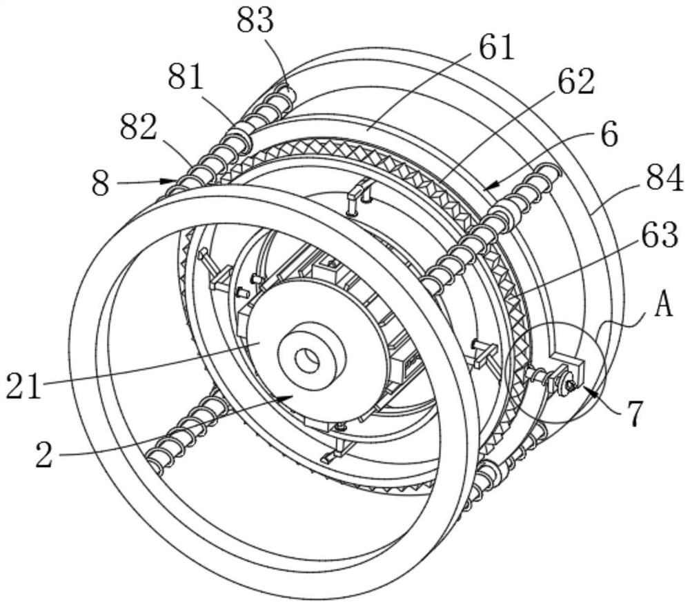
[0049] The quick installation unit 6 includes an annular mounting plate 61, a mounting bearing 62, an outer gear ring 63, a hinge support 1 64, a movable rod 65, a hinge support 2 66, a connecting rod 67, a clamping column 68, a sliding sleeve 69, a limi...
Embodiment 2
[0066] Example 2, please refer to Figure 4 , this embodiment provides a technical solution: a motor housing installation structure, the structure of this embodiment is substantially the same as that of Embodiment 1, the difference is that it also includes a fixed clamping unit 7, and the fixed clamping unit 7 includes There are convex plate 71, side plate 72, clamping rod 73, clamping block 74, clamping spring 75, round cover 76 and pull ring 77, and the side of annular mounting plate 61 is provided with convex plate 71, and the side of convex plate 71 is provided with Side plate 72, the slide hole of side plate 72 is slidably connected with clamping rod 73, and one end of clamping rod 73 is fixed with block 74, and the other end of clamping rod 73 is fixed with round cover 76, and the side of circular cover 76 is provided with There is a pull ring 77 , and one end of the clamping rod 73 close to the clamping block 74 is sleeved with a clamping spring 75 .
[0067] Rotating ...
Embodiment 3
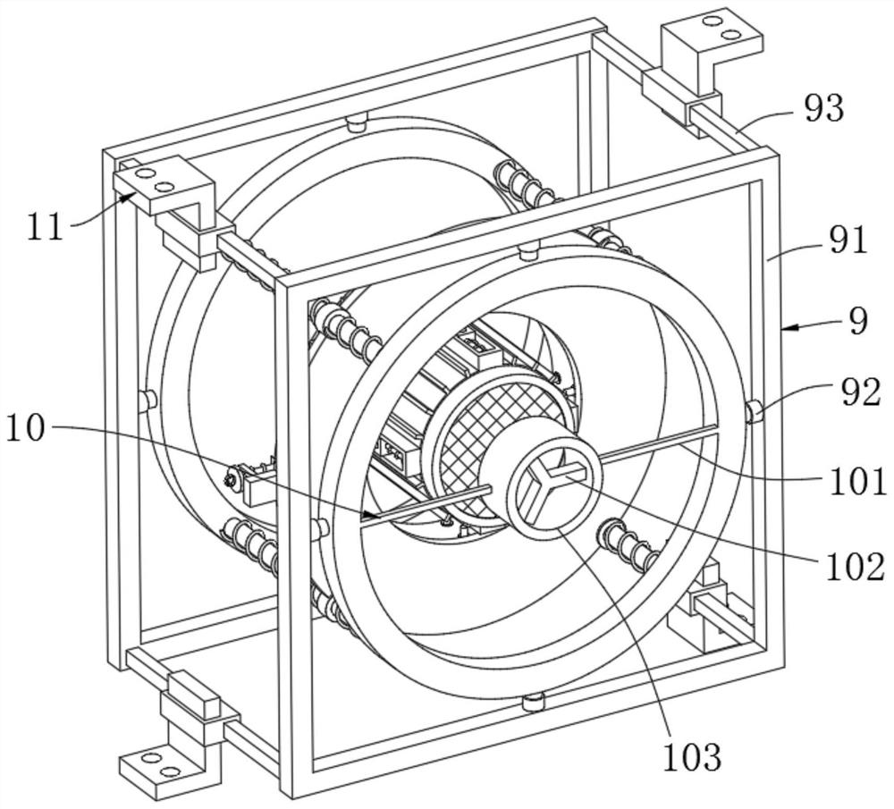
[0068] Embodiment three, please refer to Figure 1-3 , this embodiment provides a technical solution: a motor casing installation structure, this embodiment is roughly the same structure as the above embodiment, the difference is that it also includes a longitudinal shock absorbing unit 8 and a bracket unit 9, the longitudinal shock absorbing The vibration unit 8 includes a slip ring 81, a longitudinal spring 82, a longitudinal shaft 83 and a circular ring 84. The side annular array of the annular mounting plate 61 is provided with four slip rings 81, and the four slip rings 81 slide with the four longitudinal shafts 83 respectively. connection, the two ends of the four slip rings 81 are respectively connected with two circular rings 84, and the two ends of the four longitudinal shafts 83 are respectively sleeved with longitudinal springs 82, and the bracket unit 9 includes a square frame 91, a gas spring 92 and a fixed Rods 93 , the peripheral sides of each ring 84 are connec...
PUM
 Abstract
Description
Claims
Application Information