
Inner expansion cannula

A technology of inner cannula and cannula, which is applied in the field of medical equipment, and can solve the problems of increased damage, secondary injury of patients, and soft tissue blocking the operating field of view under the microscope.

Pending Publication Date: 2021-05-07
王振海
View PDF0 Cites 0 Cited by
  • Summary
  • Abstract
  • Description
  • Claims
  • Application Information

AI Technical Summary

Problems solved by technology

The inner diameter of various existing cannulas cannot be changed. During clinical operation, if the inner diameter of the cannula is too small, the soft tissue under the microscope often blocks the operating field of view; if the inner diameter is too large, the skin will be cut The incision needs to be extended or enlarged, which will cause greater damage to the patient
[0003] In clinical use, when the inner diameter of the working cannula is small, the incision during the operation is small, and the damage to the patient is also small, but the operator will spend a lot of time cleaning up the soft tissue that blocks the field of view. Low; when the inner diameter of the working sleeve increases, the incision will expand during the operation, and the damage will also increase, which is contradictory to the minimally invasive concept and will cause more secondary damage to the patient

Method used


Image

  • Inner expansion cannula
  • Inner expansion cannula
  • Inner expansion cannula

Examples


Embodiment Construction

[0026] The following non-limiting examples can enable those skilled in the art to understand the present invention more fully, but do not limit the present invention in any way.

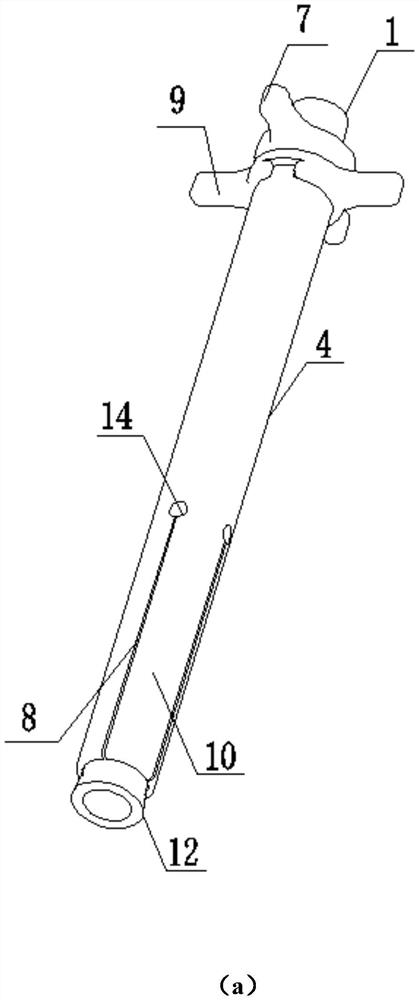
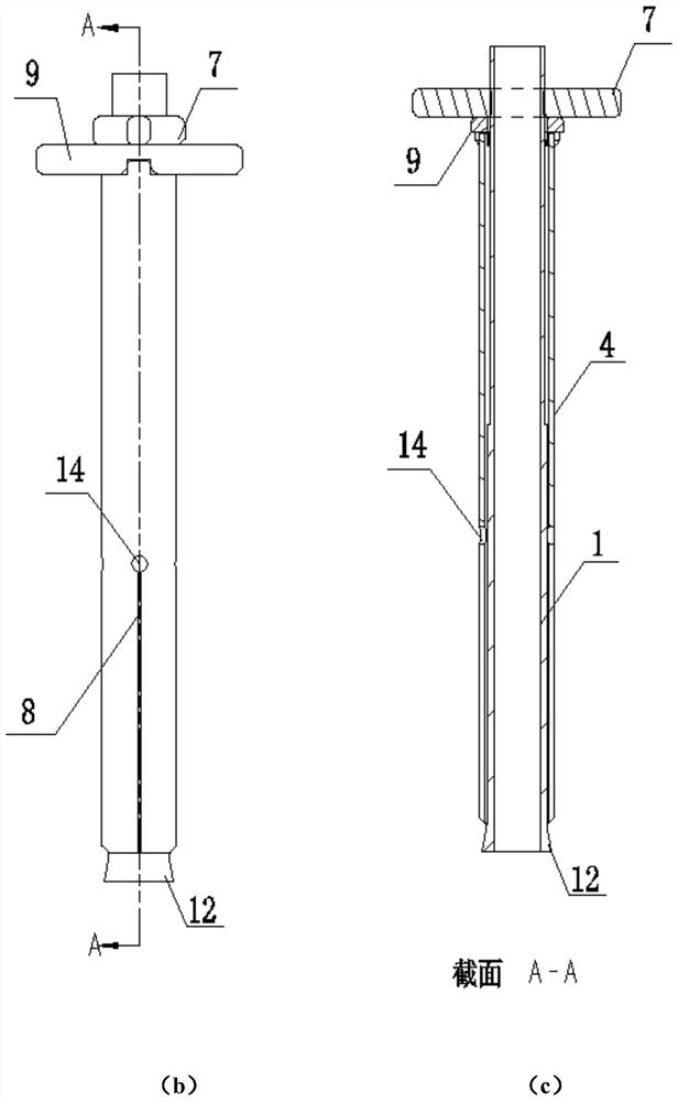
[0027] A kind of internal expansion sleeve, the structure is as Figure 1-5 As shown, including the inner casing 1, the outer casing 4 and the booster nut 7, the inner casing 1 and the outer casing 4 are provided with a pipe head end and a pipe tail end, the interior of the inner casing 1 is hollow, and the pipe of the inner casing 1 The head end 2 has a bell mouth 12 structure that expands outwards, an external thread 13 is provided on the outer wall of the pipe tail end 3 of the inner casing 1, and an internal thread matching the external thread 13 is provided on the booster nut 7; the outer casing 4 is formed by It is made of stainless steel with good biocompatibility and ductility and does not contain harmful ingredients to the human body. It is hollow inside and is set outside the inner sleeve 1...


PUM

PropertyMeasurementUnit
Lengthaaaaaaaaaa
Outer diameteraaaaaaaaaa
Lengthaaaaaaaaaa

Abstract

The invention relates to an inner expansion cannula, and belongs to the field of medical instruments. The inner expansion cannula comprises an inner cannula, an outer cannula and a power-assisted nut, wherein the inner cannula and the outer cannula are each provided with a cannula head end and a cannula tail end; the interior of the inner cannula is hollow; the cannula head end of the inner cannula is of a horn mouth structure expanding outwards; external threads are formed in the outer wall of the cannula tail end of the inner cannula; the power-assisted nut is provided with internal threads matched with the external threads; the interior of the outer cannula is hollow; the outer cannula sleeves the inner cannula; a side hole is formed in the outer cannula; longitudinal incisions are arranged in a manner of extending towards the cannula head end of the outer cannula along the side hole; the cannula wall between the adjacent longitudinal incisions forms an expansion blade; and the inner cannula is driven by rotating the power-assisted nut to move, so that the expansion blade can be expanded or closed in the radial direction. In the operation process of an endoscope, on the premise that the skin incision is not expanded, soft tissue around the operation space is expanded from the body through the inner expansion cannula, so that the operation visual field of the endoscope can be expanded, and shielding of the soft tissue under the endoscope is reduced.

Description

technical field [0001] The invention relates to an internal expansion sleeve, which belongs to the technical field of medical instruments. Background technique [0002] At present, the various working sleeves used in spinal endoscopic surgery are all expanded step by step according to their inner diameters to achieve the required operating space under the microscope. The inner diameter of various existing cannulas cannot be changed. During clinical operation, if the inner diameter of the cannula is too small, the soft tissue under the microscope often blocks the operating field of view; if the inner diameter is too large, the skin will be cut The incision needs to be extended or enlarged, which will cause greater damage to the patient. [0003] In clinical use, when the inner diameter of the working cannula is small, the incision during the operation is small, and the damage to the patient is also small, but the operator will spend a lot of time cleaning up the soft tissue ...

Claims


Application Information

Patent Timeline
IPC IPC(8): A61B17/02A61B17/00A61B17/12
CPCA61B17/00234A61B17/0218A61B17/12A61B2017/0034A61B2017/0225
Inventor 王振海王峻晨
Owner 王振海
Learn More