Automatic dismounting mechanism for test fixture

A technology for automatic disassembly and testing of fixtures, which is applied in the direction of manufacturing tools, metal processing, and metal processing equipment. It can solve problems such as the inability to guarantee test accuracy, improve disassembly efficiency, realize the disassembly process, and achieve vertical stability. Effect

Pending Publication Date: 2021-05-07
TUV RHEINLAND SHANGHAI
View PDF0 Cites 0 Cited by
  • Summary
  • Abstract
  • Description
  • Claims
  • Application Information

AI Technical Summary

Problems solved by technology

However, when faced with more than one hundred parts to be tested, it cannot be realized through manual operation, and the accuracy of the test cannot be guaranteed.

Method used


Image

  • Automatic dismounting mechanism for test fixture
  • Automatic dismounting mechanism for test fixture
  • Automatic dismounting mechanism for test fixture

Examples


Embodiment 1

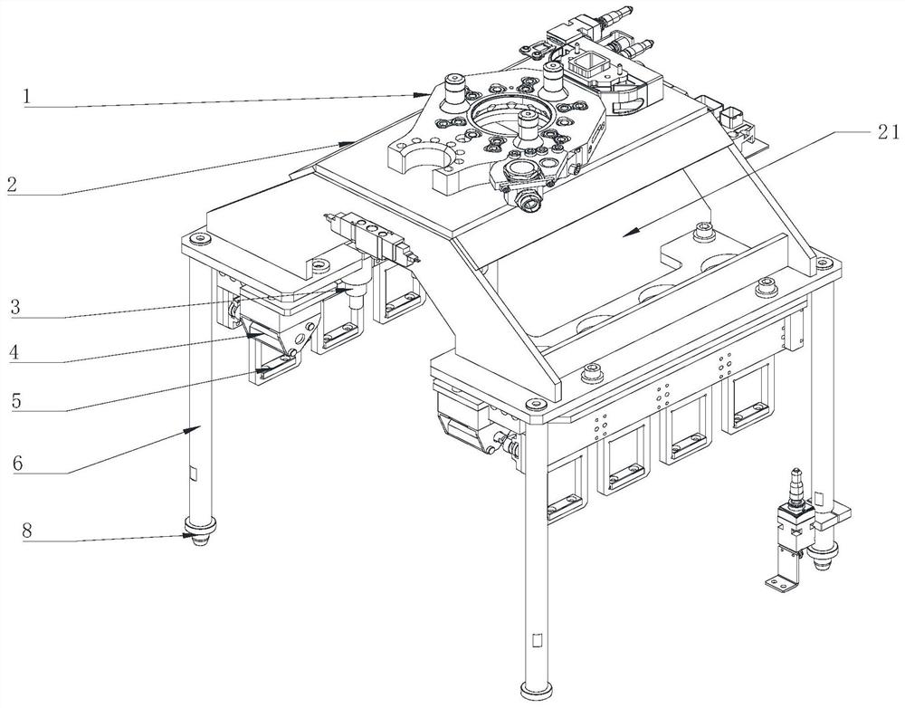
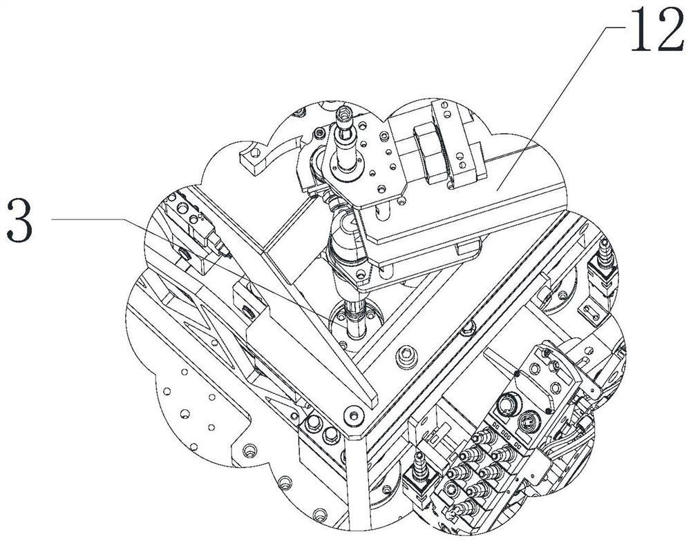
[0040] The automatic disassembly mechanism of the test fixture in this embodiment includes a fixed frame 2, a plurality of support rods 6, a robot switch plate 1, a lateral push assembly 4, a plurality of ejection assemblies 3, and a plurality of hook units 5, see figure 1 .

[0041] A plurality of support rods 6 are vertically arranged below the fixed frame 2, and the support rod 1 stands on the detection platform to realize the support of the fixed frame 1. Positioning pins 8 are arranged below the support rods 6, and the positioning pins 8 are set in the Match the guide holes on the inspection tooling.

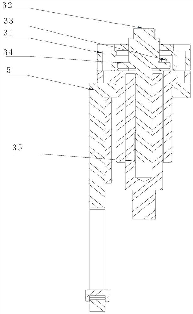
[0042] The top of fixed mount 6 is provided with hollow area 21, and tooling dismantling tightening gun 9 can pass through described hollow area 21 and be connected with the upper end of transmission rod 32 from top to bottom.

[0043] The robot switching panel 1 is arranged above the fixed frame 2 to realize quick connection with the industrial robot.

[0044] The latera...


PUM


Abstract

The invention relates to an automatic dismounting mechanism for a test fixture. The comprises a fixing frame, a plurality of supporting rods, a robot switch panel, a lateral pushing assembly, a plurality of ejection assemblies and a plurality of hook units, wherein the plurality of supporting rods are vertically arranged below the fixing frame; the robot switch panel is arranged above the fixing frame; the lateral pushing assembly is connected onto the fixing frame; the plurality of ejection assemblies are connected onto the lateral pushing assembly, and can abut against a conical nut in a test pipe fitting, so that the conical nut can be separated from the test pipe fitting; the plurality of hook units are connected onto the lateral pushing assembly; and the hook units are driven by the lateral pushing assembly to horizontally move and are hooked to the upper portion of the test fixture. Compared with the prior art, the automatic dismounting mechanism for the test fixture can be matched with a full-automatic dismounting process, and accordingly, large-batch, high-precision and automatic detection fixture dismounting and part discharging are realized.

Description

technical field [0001] The invention relates to a disassembly mechanism, in particular to an automatic disassembly mechanism of a test fixture. Background technique [0002] In the current field of industrial parts inspection, it is necessary to load the parts to be tested into the inspection tool, and then put the inspection tool on the corresponding position of the inspection platform to complete the loading process, and then realize the locking of the inspection tool and the parts to be tested through the locking mechanism. After the inspection process is completed, the inspection tooling and the parts to be tested are taken off from the inspection platform and placed in the storage area to complete the blanking process. [0003] In the process of testing the mechanical properties of pipe fittings, the current loading and unloading processes are all manual operations. The testing tooling and the parts to be tested are all metal materials, and the weight is relatively larg...

Claims


Application Information

Patent Timeline
IPC IPC(8): B23P19/00
CPCB23P19/00
Inventor 顾蔚
Owner TUV RHEINLAND SHANGHAI
Why Eureka
Try Eureka