Surface grinding device for circular cutting board machining

A cutting board and circular technology, which is applied in the field of surface grinding devices for processing circular cutting boards, achieves the effects of improving grinding speed, quick placement and removal, and easy grinding

Pending Publication Date: 2021-05-07
万小华
View PDF7 Cites 1 Cited by
  • Summary
  • Abstract
  • Description
  • Claims
  • Application Information

AI Technical Summary

Problems solved by technology

[0005] In order to overcome the shortcomings of the need to manually move the sanding sheet repeatedly on the surface of the circular wooden block for grinding and deburring, the technical problem to be solved by the pre

Method used


Image

  • Surface grinding device for circular cutting board machining
  • Surface grinding device for circular cutting board machining
  • Surface grinding device for circular cutting board machining

Examples


Embodiment 1

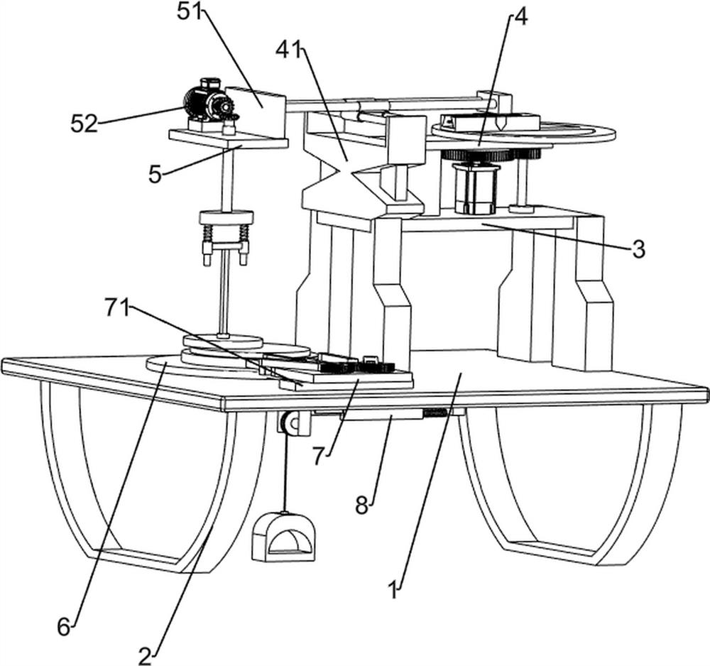
[0025] A surface grinding device for circular chopping board processing, such as Figure 1-3 As shown, it includes a bottom plate 1, a tripod 2, a support frame 3, a rotating mechanism 4, a grinding mechanism 5 and a backing plate 6. Two tripods 2 are symmetrically connected to the bottom of the bottom plate 1, and a support is connected to the top right side of the bottom plate 1. Frame 3, a rotating mechanism 4 is installed on the support frame 3, a grinding mechanism 5 is connected to the rotating mechanism 4, and a backing plate 6 is connected to the left side of the bottom plate 1 top.

[0026] The rotating mechanism 4 includes a special-shaped plate 41, a servo motor 42, a first rotating shaft 43, a full gear set 44, a turntable 45, a first connecting block 46, a screw rod 47, a slider 48, a second connecting block 49, and a first sliding rod 410 , guide rail 411 and the second slide bar 412, the left side of the support frame 3 top is connected with a special-shaped pla...

Embodiment 2

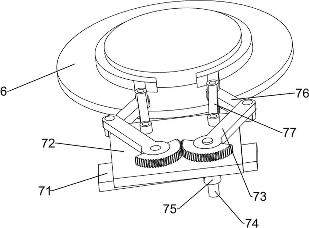
[0030] On the basis of Example 1, such as figure 1 and Figure 4As shown, a clamping mechanism 7 is also included, and the clamping mechanism 7 includes a support block 71, a connecting plate 72, a sector gear rod 73, a third rotating shaft 74, a scroll spring 75, a clamping rod 76 and a connecting rod 77, and the bottom plate 1 The top left front side is connected with a support block 71, the top of the support block 71 is connected with a connecting plate 72, and the right part of the connecting plate 72 is connected with a third rotating shaft 74 in a rotational manner, and the bottom end of the third rotating shaft 74 runs through the supporting block 71 and the bottom plate 1, and the third rotating shaft A scroll spring 75 is connected between 74 and the base plate 1, a sector gear lever 73 is connected to the third rotating shaft 74 top, and a sector gear lever 73 is also rotatably connected to the left part of the connecting plate 72, and the two sector gear levers 73 ...

Embodiment 3

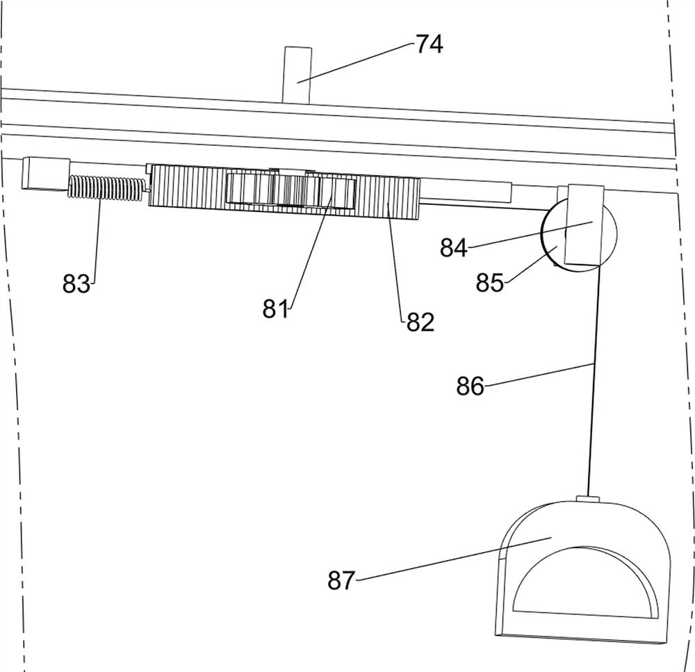
[0033] On the basis of Example 2, such as figure 1 and Figure 5 As shown, pedal mechanism 8 is also included, and pedal mechanism 8 includes spur gear 81, rack 82, back-moving spring 83, fixed mount 84, belt pulley 85, flat belt 86 and pedal frame 87, and the third rotating shaft 74 bottoms A spur gear 81 is connected, a rack 82 is slidably connected to the left front side of the bottom of the base plate 1, the rack 82 meshes with the spur gear 81, a return spring 83 is connected between the rack 82 and the base plate 1, and a fixed Frame 84, fixed frame 84 is positioned at the left side of tooth bar 82, is connected with belt pulley 85 in rotation on fixed frame 84, is connected with flat belt 86 on the left side of tooth bar 82, and flat belt 86 bottom ends around belt pulley 85, and flat belt 86 The bottom end is connected with pedal frame 87.

[0034] When two clamp bars 76 are to be separated, the pedal frame 87 can be stepped on downwards with the feet, and the pedal ...


PUM


Abstract

The invention relates to a grinding device, in particular to a surface grinding device for circular cutting board machining. According to the surface grinding device for circular cutting board machining, the surface of a circular wood block can be automatically ground, time and labor can be saved, and the grinding speed can be increased. The surface grinding device for round cutting board machining is characterized by comprising a bottom plate, a supporting frame and a base plate, and two foot stools are connected to the bottom of the bottom plate; the supporting frame is connected to one side of the top of the bottom plate, a rotating mechanism is installed on the supporting frame, and a grinding mechanism is connected to the rotating mechanism; and the other side of the top of the bottom plate is connected with the base plate. According to the surface grinding device for circular cutting board machining, the grinding mechanism can move along the circular wood block through the rotating mechanism, the grinding mechanism moves along the circular wood block and can polish and remove burrs on the surface of the circular wood block in all directions, and therefore the effects that the surface of the circular wood block can be automatically polished, time and labor are saved, and the polishing speed can be increased are achieved.

Description

technical field [0001] The invention relates to a grinding device, in particular to a surface grinding device for processing circular chopping boards. Background technique [0002] The chopping board refers to the utensils that are placed underneath when hammering, cutting, chopping, or smashing things. It is generally used for cooking. When producing a round cutting board, first cut the large round wooden board into round wooden blocks of suitable size. , and then process the round wood block to make a round cutting board. The surface of the round wood block after preliminary cutting is relatively rough, and there will be more burrs on the surface of the round wood block. It needs to be polished and deburred before proceeding to the next step Processing. At present, the grinding and deburring of the surface of the round wooden block is generally carried out manually. When the manual grinding and deburring work is performed manually, the sanding sheet is used to move the san...

Claims


Application Information

Patent Timeline
IPC IPC(8): B24B9/18B24B41/02B24B41/06B24B47/20B24B47/22
CPCB24B9/18B24B47/20B24B41/067B24B41/02B24B47/22
Inventor 万小华
Owner 万小华
Why Eureka
Try Eureka