
Draught fan device and electric appliance using draught fan

A fan and electrical appliance technology, applied in the field of refrigeration equipment, can solve the problems of increased pressure difference between the inlet and outlet of the fan, increased leakage, etc.

Pending Publication Date: 2021-05-07
GREE ELECTRIC APPLIANCES INC
View PDF0 Cites 0 Cited by
  • Summary
  • Abstract
  • Description
  • Claims
  • Application Information

AI Technical Summary

Problems solved by technology

[0004] However, these structural forms have a resistance channel size that is relatively constant. As the fan speed increases, the pressure difference between the inlet and outlet of the fan increases, and the leakage increases significantly.

Method used


Image

  • Draught fan device and electric appliance using draught fan
  • Draught fan device and electric appliance using draught fan
  • Draught fan device and electric appliance using draught fan

Examples


Embodiment Construction

[0044] The present disclosure is described in detail below. In the following paragraphs, different aspects of the embodiments are defined in more detail. Aspects so defined may be combined with any other aspect or aspects unless specifically stated otherwise. In particular, any feature considered to be preferred or advantageous may be combined with one or more other features which are considered to be preferred or advantageous.

[0045] Terms such as "first" and "second" appearing in the present disclosure are only for convenience of description to distinguish different components with the same name, and do not indicate a sequence or a primary and secondary relationship.

[0046] In addition, when an element is referred to as being "on" another element, the element may be directly on the other element or may be indirectly on the another element with an interposed therebetween. More intermediate elements. Also, when an element is referred to as being "connected to" another e...


PUM


Abstract

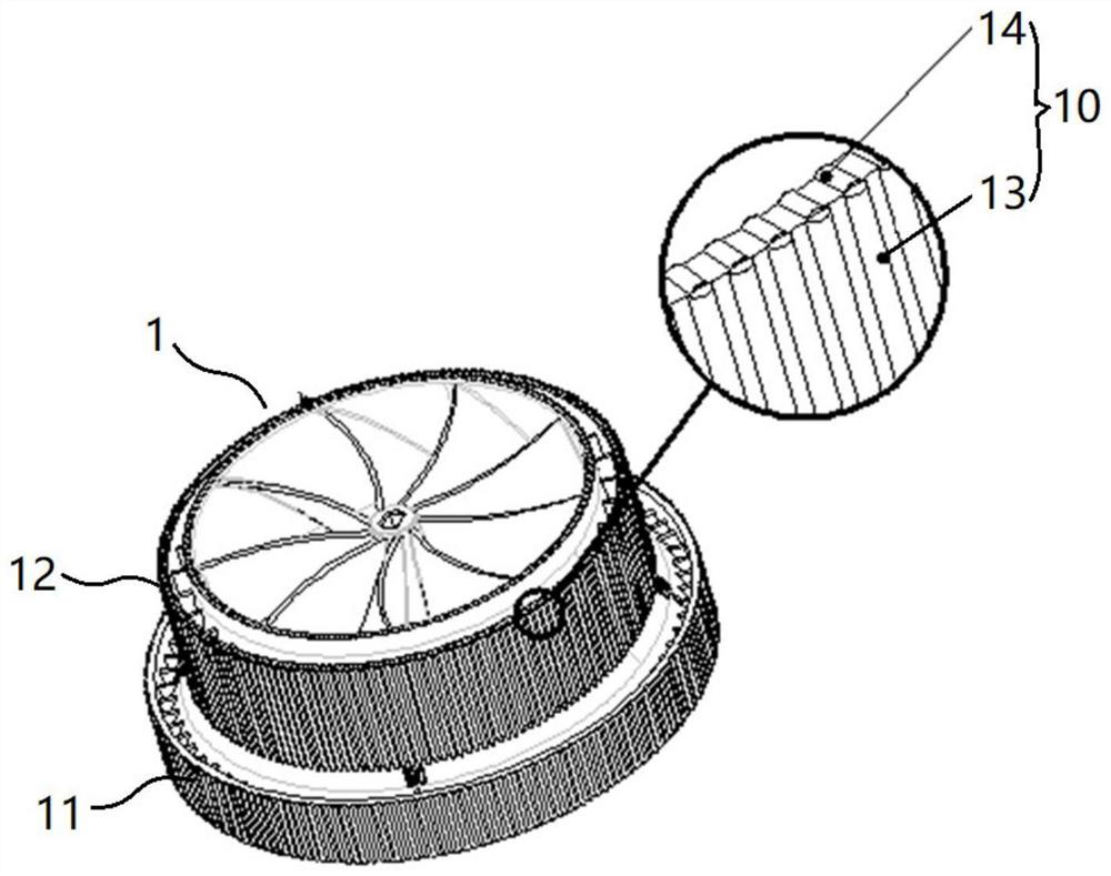
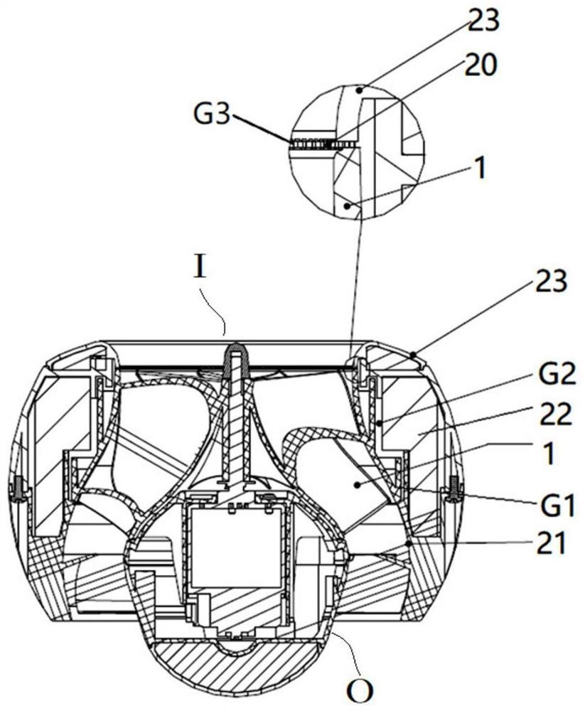
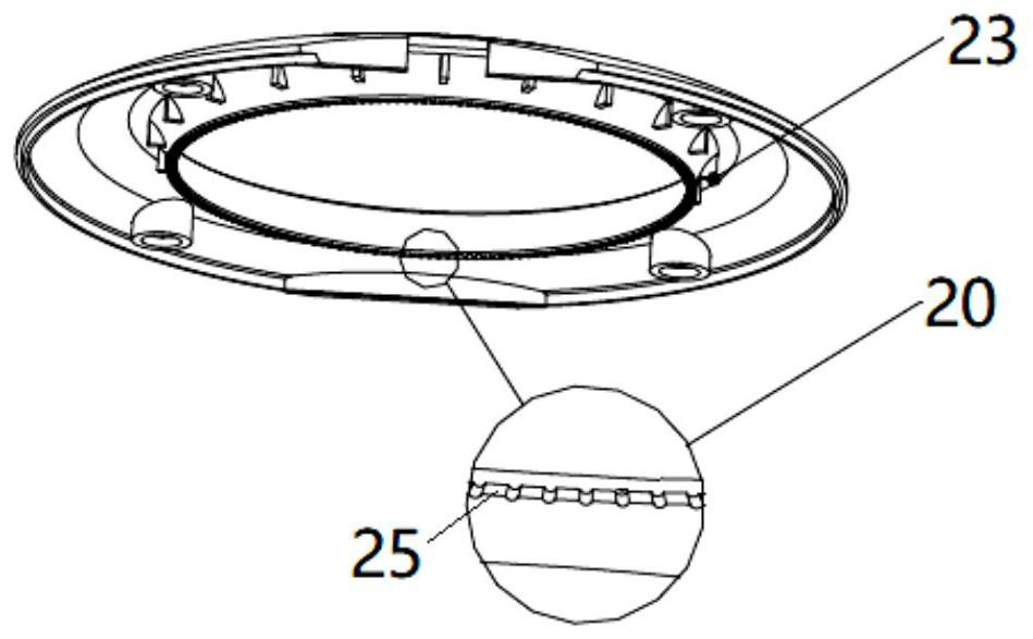
The invention relates to a draught fan device and an electric appliance using the draught fan. The draught fan device comprises a volute (2) and an impeller (1); and the impeller (1) is rotatably arranged in the volute (2) around the axis of the impeller (1), a leakage gap is formed between the impeller (1) and the volute (2), and at least part of the wall face, forming the leakage gap, of the impeller (1) is provided with a first flow disturbing structure (10) which is configured to disturb airflow in the leakage gap.

Description

technical field [0001] The present disclosure relates to the technical field of refrigeration equipment, in particular to a fan device and an electrical appliance using the fan. Background technique [0002] The fan needs to rotate because the moving blade needs to rotate, and there is a gap between it and the volute. Due to the high pressure at the outlet of the moving blade and the pressure difference between the outlet of the fan and the pressure difference between the inlet of the fan, there will be leakage between the moving blade and the volute, also known as volume loss. [0003] In the related art, the gap between the moving fan blade and the volute is mainly reduced, or a labyrinth structure is adopted, so that the leakage gas passes through the labyrinth channel to form a resistance area to reduce fan leakage. [0004] However, in these structural forms, the size of the resistance channel is relatively constant. As the fan speed increases, the pressure difference ...

Claims


Application Information

Patent Timeline
Patent Type & Authority Applications(China)
IPC IPC(8): F04D29/28F04D29/44
CPCF04D29/283F04D29/441
Inventor 池晓龙刘煜张一帆张碧瑶杨泽寰张仕强
Owner GREE ELECTRIC APPLIANCES INC
Learn More