
Autonomous firing line shearing device

A cutting device and autonomous technology, applied in the mechanical field, can solve the problems of high manufacturing cost, complicated mechanism of falling off plugs, damage to the connection of ignition wires, etc., and achieve the effect of wide range of wire diameters

Active Publication Date: 2021-05-07
中国船舶重工集团有限公司第七一0研究所 +1
View PDF6 Cites 0 Cited by
  • Summary
  • Abstract
  • Description
  • Claims
  • Application Information

AI Technical Summary

Problems solved by technology

[0003] Both of the above two methods have defects: the method of directly pulling off the firing wire may easily cause damage to the connection of the firing wire at the end of the launch tube; the use of a drop-off plug mechanism to separate the firing wire is complicated and the manufacturing cost is high

Method used


Image

  • Autonomous firing line shearing device
  • Autonomous firing line shearing device
  • Autonomous firing line shearing device

Examples


Embodiment 1

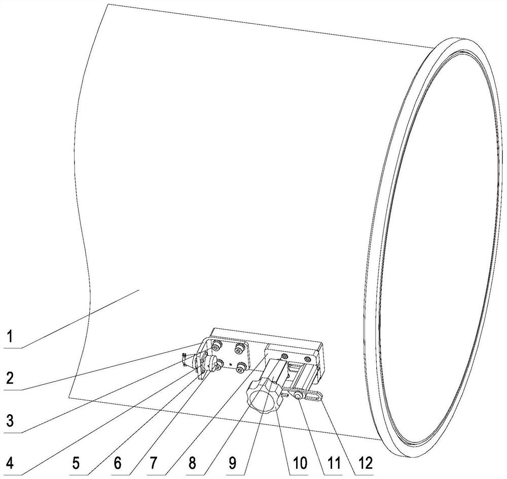
[0037] This embodiment provides an autonomous firing wire cutting device, which can cut off the firing wire autonomously, avoid damage to the connection of the firing wire at the end of the launch tube, effectively control the separation of the carrier (ammunition) from the launch tube, and be safe and reliable in use.

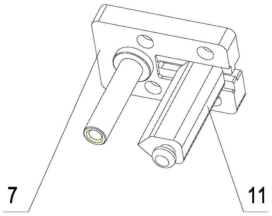
[0038] Such as Figure 1-Figure 7 As shown, the shearing device is installed on the launch tube 1, including: a connector mounting seat 2, a socket 4, a seat body 7, a square column 9, a handle 10, a side blade body 11 and a wire retaining plate 12; a fire wire plug 14 It is integrally connected with the ignition wire 15, and the ignition wire 15 is connected with the cutting device through the ignition wire plug 14.

[0039] specific:

[0040] A boss is left on the outer circumference of the launch tube 1, and eight screw holes for installing the shearing device are left on the boss;

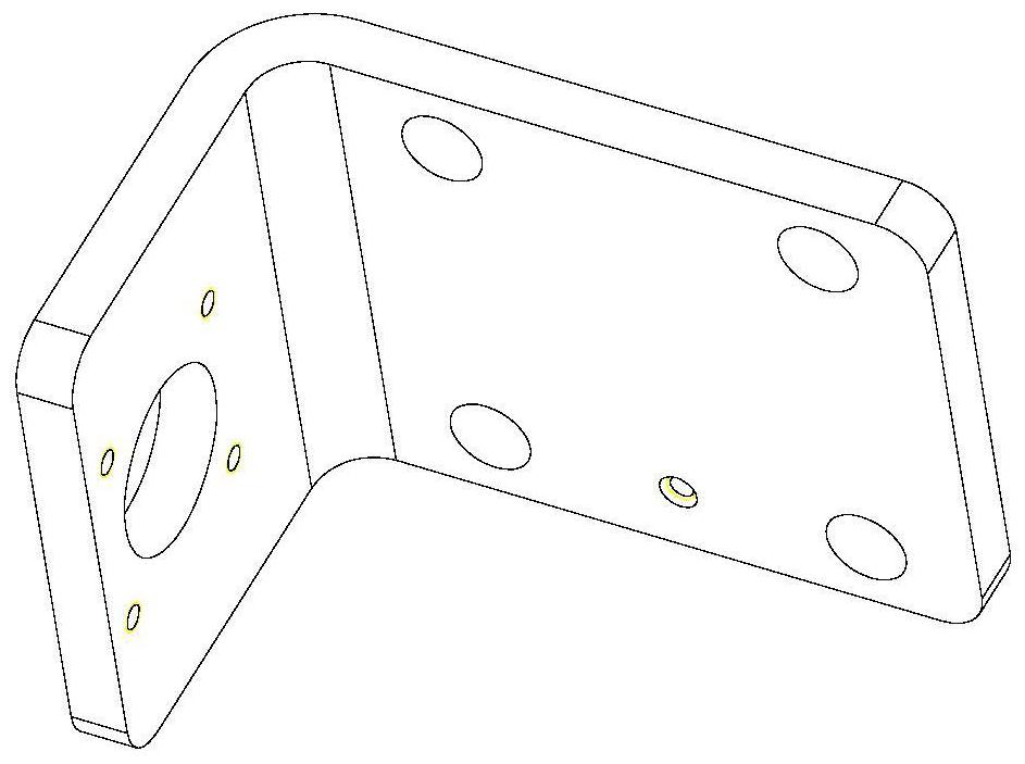
[0041] Such as figure 2 As shown, the connector mounting seat 2 is a 9...

Embodiment 2

[0057] On the basis of the above-mentioned embodiment 1, because the cutting device utilizes the change of the gap between its side and the side blade body 11 when the square column 9 rotates to realize the shearing of the blade of the side blade body 11 to the firing line 15, therefore the Replacing the square column 9 with other rotary structures (i.e. rotating bodies) with different wall thicknesses along the circumferential direction can also achieve the purpose of automatically cutting the firing line 15, such as a cam; the distance between the side blade body and the rotating body ensures: When the side with the smallest wall thickness of the rotating body was opposite to the side where the blade of the side blade body was located, the blade of the side blade body did not touch the firing line between the side blade body 11 and the rotating body; When the side where the edge of the blade body is located is opposite, the blade of the side blade body can cut off the firing ...


PUM


Abstract

The invention discloses an autonomous firing line shearing device. According to the autonomous firing line shearing device, a firing line is automatically sheared through separation movement generated by the firing line, the situation that the connecting position of the firing line at a launching tube end is damaged is avoided, ammunition and the launching tube are effectively controlled to be separated, and use is safe and reliable. The shearing device comprises a connector mounting seat, a socket, a seat body, a rotating body, a handle, a side blade body and a wire baffle plate; the connector mounting seat and the seat body are fixed on a boss on the peripheral surface of the launching tube; the socket is fixed on the connector mounting seat; the rotating body is mounted on a cylindrical rod on the surface of the seat body in a sleeving mode and can rotate around the axis of the cylindrical rod on the seat body; the rotating body is of a rotary structure with different wall thicknesses in the circumferential direction, and therefore the gap between the side face of the rotating body and the side where a cutting edge of the side blade body is located can be changed through rotation of the rotating body; and the firing line is inserted into the socket through a firing line plug at the end part of the firing line after being wound on the rotating body by two or more circles. The cutting edge of the side blade body can cut the firing line by utilizing the change of the gap between the rotating body and the side blade body when the rotating body rotates.

Description

technical field [0001] The invention relates to a firing wire shearing device in the process of pneumatically projecting a carrier or gunpowder to launch ammunition, in particular to an autonomous firing wire cutting device, which belongs to the field of machinery. Background technique [0002] In the process of general pneumatic projectile carrier or gunpowder launching ammunition, the firing line connecting the carrier (ammunition) and the launch tube is directly pulled off after the carrier (ammunition) flies away from the launch tube, and no mechanical device is used to cut the firing line; some pneumatic projectiles In the process of launching ammunition from the carrier or gunpowder, the firing wire is separated by using a drop-off plug mechanism. [0003] Above-mentioned two kinds of methods all have defects: adopting the way of directly pulling off the firing wire will easily cause damage to the connection of the firing wire at the end of the launch tube; adopting a ...

Claims


Application Information

Patent Timeline
Patent Type & Authority Applications(China)
IPC IPC(8): F41F1/00B21F11/00
CPCF41F1/00B21F11/00
Inventor 刘威宋向华廖贵超
Owner 中国船舶重工集团有限公司第七一0研究所
Learn More