Rail stress measuring device and method

A technology of stress measurement and position measurement, which is applied in the direction of measuring devices, measuring forces, instruments, etc., can solve problems such as low efficiency and cumbersome rail stress detection process

Pending Publication Date: 2021-05-07
NORTHEAST FORESTRY UNIVERSITY
View PDF0 Cites 2 Cited by
  • Summary
  • Abstract
  • Description
  • Claims
  • Application Information

AI Technical Summary

Problems solved by technology

[0005] This application proposes a rail stress measurement device and method to so...

Method used


Image

  • Rail stress measuring device and method
  • Rail stress measuring device and method
  • Rail stress measuring device and method

Examples


Embodiment Construction

[0029] In order to make the purpose, technical solution and advantages of the present application clearer, the technical solution of the present application will be clearly and completely described below in conjunction with specific embodiments of the present application and corresponding drawings. Apparently, the described embodiments are only some of the embodiments of the present application, rather than all the embodiments. Based on the embodiments in this application, all other embodiments obtained by persons of ordinary skill in the art without making creative efforts belong to the scope of protection of this application.

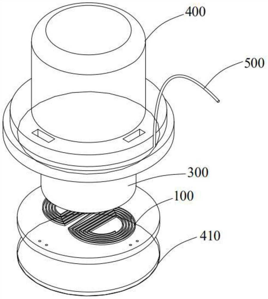
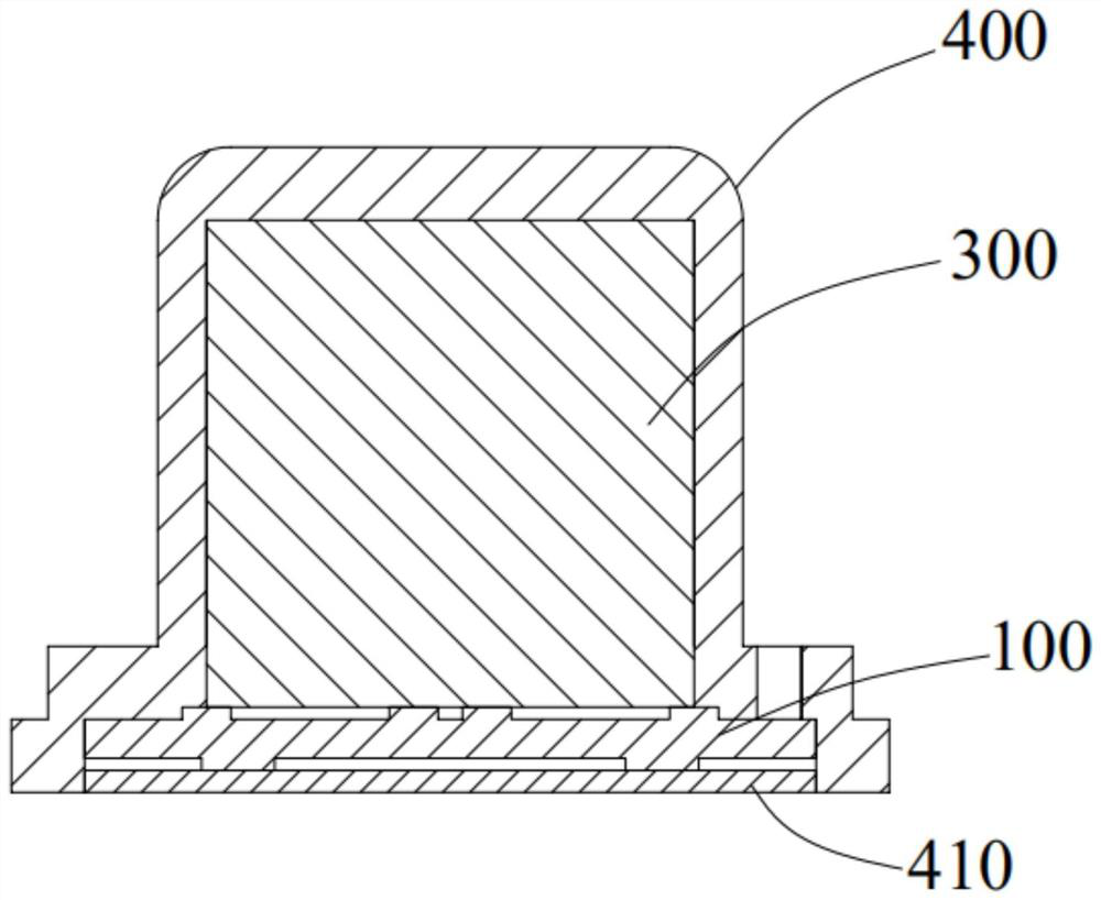
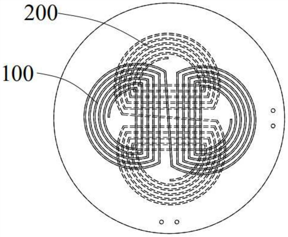
[0030] figure 1 A rail stress measuring device according to an embodiment of the present application is schematically shown. The rail stress measuring device comprises a first coil 100, a second coil 200, a magnetic part 300, a power supply part and a control part; wherein the magnetic part 300 is arranged near the first coil 100 and the second coil ...


PUM


Abstract

The invention discloses a rail stress measuring device and method. The rail stress measuring device comprises a first coil, a second coil, a magnetic part, a power supply part and a control part, wherein the magnetic part is arranged close to the first coil and the second coil; the power supply part is used for introducing alternating current into the first coil so as to generate first ultrasonic transverse waves in the rail, the vibration direction of the first ultrasonic transverse waves is the same as the length direction of the rail, and it should be noted that during measurement, the first coil should be close to the detected rail, and the power supply part is also used for introducing alternating current into the second coil, the vibration direction of the second ultrasonic transverse wave is perpendicular to the length direction of the rail, and correspondingly, the second coil is also close to the detected rail; and the control part is used for measuring the propagation speed of the first ultrasonic transverse wave and the second ultrasonic transverse wave in the rail. The rail stress measuring device is ingenious in structure, simple in operation during measurement and capable of effectively improving the rail stress detection efficiency.

Description

technical field [0001] The present application relates to the field of stress detection, in particular to a rail stress measurement device and method. Background technique [0002] Rail is an important part of railway traffic. Whether it is seamless rail or ordinary rail, the alternation of seasons, temperature changes, maintenance and construction, and even the normal operation of trains on rails will cause changes in rail stress, and changes in stress will cause rails to exist. The risk of broken rails and increased rails poses a hidden danger to the safety and stability of railway traffic. [0003] The current detection methods are mainly divided into destructive methods and non-destructive methods. Damage methods mainly include blind hole method, strip cutting method, split method and so on. Non-destructive methods mainly include X-ray diffraction method, neutron diffraction method, ultrasonic method and so on. The damage method cannot complete online detection and da...

Claims


Application Information

Patent Timeline
IPC IPC(8): G01L1/25
CPCG01L1/255
Inventor 邢涛朱天龙王崇
Owner NORTHEAST FORESTRY UNIVERSITY
Why Eureka
Try Eureka