Energy storage mechanism for spring operating mechanism

A technology of operating mechanism and energy storage mechanism, which is applied in the direction of protection switch operation/release mechanism, etc., and can solve the problems of poor stability of spring operating mechanism and large lateral force component of energy storage pull rod, etc.

Pending Publication Date: 2021-05-07
HENAN PINGGAO ELECTRIC +2
View PDF8 Cites 1 Cited by
  • Summary
  • Abstract
  • Description
  • Claims
  • Application Information

AI Technical Summary

Problems solved by technology

[0003] The object of the present invention is to provide an energy storage mechanism for a spring operating mechanism, which is used to solve the problem of the current energy storage mechanism for a spring operating mechanism due to the existence of accumulated errors that cause the energy storage pull rod to receive a large lateral component force. The technical problem of poor stability of the operating mechanism

Method used


Image

  • Energy storage mechanism for spring operating mechanism
  • Energy storage mechanism for spring operating mechanism
  • Energy storage mechanism for spring operating mechanism

Examples


specific Embodiment 1

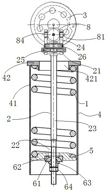
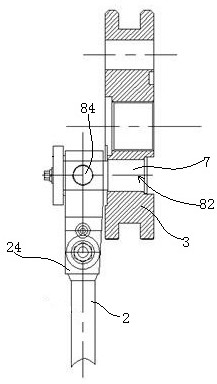
[0037]Such asFigure 1 to 9 As shown, the spring optic mechanism includes a frame, the energy storage spring 1, the energy storage rod 2, the drive wheel 3, wherein the transmission wheel 3 rotates on the rack, and the rack is provided with the drive wheel. Mounting axis. A spring barrel 4 is also provided on the frame, and the energy storage spring 1 is disposed in the spring barrel 4, and the upper end of the energy storage rod 2 is connected to the drive wheel 3, and the lower end is a spring fit end 22, the spring fit end 22 The spring pressure plate 5 is provided, and the lower end of the energy storage spring 1 is in contact with the spring block, and the upper end is in contact with the spring cartridge 4, and the spring pressure plate 5 is guided in the extending direction of the reservoir spring 1 in the spring cartridge 4. In the present invention, the extending direction of the energy storage spring 1 is a compression extension direction of the storage energy spring 1. In ...


PUM


Abstract

The invention relates to an energy storage mechanism for a spring operating mechanism. The invention provides an energy storage mechanism for a spring operating mechanism. The spring operating mechanism comprises a rack, an energy storage spring, an energy storage pull rod and a transmission part; a connecting block is hinged to the matched end of the transmission part and rotationally arranged on the transmission part; the hinge axis of the connecting block and the matched end of the transmission part is a connecting block hinge axis; the rotating axis of the connecting block and the transmission part is a connecting block rotating axis; the connecting block hinge axis and the connecting block rotating axis are coplanar and perpendicularly intersect with each other; the connecting block rotating axis is parallel to the rotating axis of the transmission part relative to the rack; the normal direction of the plane where the connecting blockrotating axis and the connecting block hinged axis are located is the extending direction of the energy storage spring; a lug plate can swing relative to the connecting block, so that lateral component force generated when the center line of an energy storage pull rod and the center line of the energy storage spring are not collinear due to assembly accumulative errors is reduced or eliminated, so that the stability of the energy storage mechanism for the spring operating mechanism is improved.

Description

Technical field[0001]The present invention relates to an energy storage mechanism for a spring actuator.Background technique[0002]Since the spring opener structure is simple, the cost is low, therefore widely used in the 220kV level and the following circuit breaker mechanism. During the operation of the mechanism closing, due to the presence of the accumulation error during the assembly process, the ratchet connection of the energy storage tie rod and the spring operation mechanism is easily skewed to the ratchet axial direction, and the energy storage pulling rod is larger, The stability of the spring octic mechanism is much more affected.Inventive content[0003]It is an object of the present invention to provide a spring operating mechanism for energy storage mechanism for solving the current spring operating mechanism for energy storage mechanism to cause a lateral force of the energy storage tie rod to be largely caused by the presence of the accumulation error. Technical issues...

Claims


Application Information

Patent Timeline
Patent Type & Authority Applications(China)
IPC IPC(8): H01H71/12H01H71/10
CPCH01H71/12H01H71/10
Inventor 吕晓峰郭锴王志峰李云龙王慧慧汪盛朱清杰范向新屈远韶张坤子袁奕
Owner HENAN PINGGAO ELECTRIC
Why Eureka
Try Eureka