
Filtering antenna, antenna array and wireless device

A filter antenna and antenna array technology, applied in the field of wireless communication and antenna, can solve the problems that the antenna has no filtering function, waste of space, and less research on filter antennas in the millimeter frequency band, and achieves excellent suppression level, reduced physical size, and good impedance. matching effect

Active Publication Date: 2021-05-07
SHENZHEN SOUTH STAR TECH
View PDF6 Cites 0 Cited by
  • Summary
  • Abstract
  • Description
  • Claims
  • Application Information

AI Technical Summary

Problems solved by technology

In addition, the antenna itself does not have a filtering function, which will cause some unnecessary frequency band signals to be transmitted or received, and it is a waste of space to place two passive devices at the front end of the radio frequency system. tor and the function of the antenna as a filter antenna
[0003] With the continuous development of mobile communications, China has released the future 5G millimeter wave frequency band (24.75-27.5GHz) in recent years. There are still few researches on filter antennas, and the society urgently needs filter antennas for millimeter frequency bands

Method used


Image

  • Filtering antenna, antenna array and wireless device
  • Filtering antenna, antenna array and wireless device
  • Filtering antenna, antenna array and wireless device

Examples


Embodiment Construction

[0060] Hereinafter, some specific embodiments of the present invention will be described in detail with reference to the accompanying drawings. The same reference numbers may be used in different drawings to identify the same or similar elements. In the following description, for purposes of explanation and not limitation, specific details are set forth, such as specific structures, techniques, etc., in order to provide a thorough understanding of various aspects of the claimed invention. It will be apparent, however, to one skilled in the art having the benefit of this disclosure, that various aspects of the claimed invention may be practiced in other examples that depart from these specific details. In some instances, descriptions of well-known devices, devices, structures, and methods are omitted so as not to obscure the description of the embodiments of the present disclosure with unnecessary detail.

[0061] In the following description, terms commonly employed by those ...


PUM


Abstract

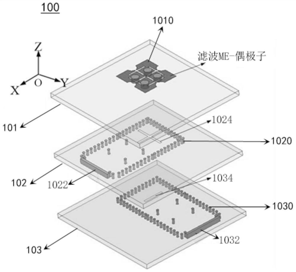
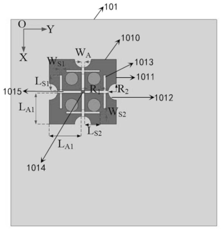
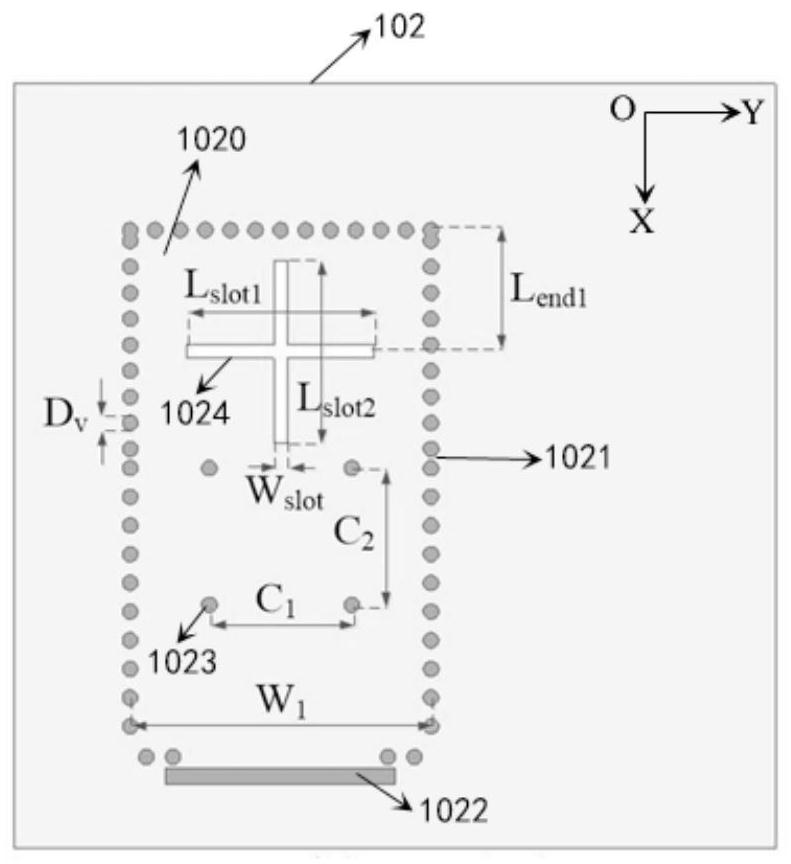
The invention provides a filtering antenna which is characterized in that the filtering antenna comprises a first layer, a second layer and a third layer, the first layer is provided with a radiation electric dipole unit, the radiation electric dipole unit is provided with a plurality of electric dipole patches, and the electric dipole patches are provided with arc-shaped notches and grooves; the second layer is provided with a first feed unit, and the first feed unit is provided with a first filtering cavity; and the third layer is provided with a second feed unit, and the second feed unit is provided with a second filtering cavity.

Description

technical field [0001] The invention relates to the field of wireless communication, in particular to the field of antennas. Background technique [0002] Filters and antennas are two important passive components at the front end of an RF system for wireless devices. The function of the filter is to only allow the signals of a part of the frequency band to pass through and suppress the signals of other frequency bands. With the development of wireless communication, there are many frequency bands of antennas. In order to filter the signals of these different frequency bands, low-pass filters and high-pass filters are used. Filters, band-pass filters, band-stop filters, etc., among which the most widely used is the band-pass filter. In addition, the antenna itself does not have a filtering function, which will cause some unnecessary frequency band signals to be transmitted or received, and it is a waste of space to place two passive devices at the front end of the radio freq...

Claims


Application Information

Patent Timeline
Patent Type & Authority Applications(China)
IPC IPC(8): H01Q1/36H01Q1/50H01Q15/24H01Q13/10H01P1/207H01P1/212
CPCH01Q1/36H01Q1/50H01Q15/24H01Q13/10H01P1/207H01P1/212
Inventor 梁胜冯波涛陈均龙
Owner SHENZHEN SOUTH STAR TECH
Learn More