
Press-fit jig assembly and vacuum press-fit equipment

A pressing jig and jig technology, applied in electrical components, laminated printed circuit boards, printed circuit manufacturing, etc., can solve problems such as inability to perform double-sided three-dimensional lamination

Pending Publication Date: 2021-05-07
SHANGHAI LANGHUA SCI & TRADING
View PDF1 Cites 2 Cited by
  • Summary
  • Abstract
  • Description
  • Claims
  • Application Information

AI Technical Summary

Problems solved by technology

[0004] The invention provides a pressing jig assembly and vacuum pressing equipment to solve the problem that double-sided three-dimensional pressing cannot be performed

Method used


Image

  • Press-fit jig assembly and vacuum press-fit equipment
  • Press-fit jig assembly and vacuum press-fit equipment
  • Press-fit jig assembly and vacuum press-fit equipment

Examples


Embodiment Construction

[0065]The following will clearly and completely describe the technical solutions in the embodiments of the present invention with reference to the accompanying drawings in the embodiments of the present invention. Obviously, the described embodiments are only some, not all, embodiments of the present invention. Based on the embodiments of the present invention, all other embodiments obtained by persons of ordinary skill in the art without making creative efforts belong to the protection scope of the present invention.

[0066] The terms "first", "second", "third", "fourth", etc. (if any) in the description and claims of the present invention and the above drawings are used to distinguish similar objects and not necessarily Describe a specific order or sequence. It is to be understood that the data so used are interchangeable under appropriate circumstances such that the embodiments of the invention described herein can be practiced in sequences other than those illustrated or ...


PUM


Abstract

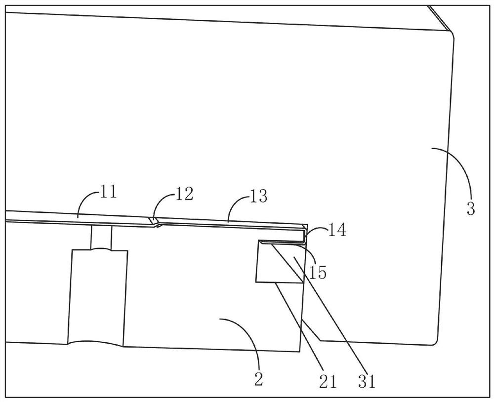
The invention provides a press-fit jig assembly and vacuum press-fit equipment. The jig assembly comprises a jig cover plate, a jig bottom plate and a plurality of force-gathering press-fit convex blocks. A first step surface is arranged on the upper surface of the jig bottom plate, a bottom plate step surface is arranged on the upper surface of the jig bottom plate, the shape of the bottom plate step surface is matched with that of the first step surface, and when the workpiece to be pressed is arranged on the jig bottom plate in a sleeving mode, the upper surface of the jig bottom plate is attached to the first step surface of the workpiece to be pressed; a plurality of embedding holes penetrating through the upper surface and the lower surface of the jig cover plate are formed in the edge of the jig cover plate, the force gathering pressing protruding blocks are embedded in the embedding holes, and the maximum thickness of the force gathering pressing protruding blocks is larger than the length of the embedding holes; and the workpiece to be pressed is arranged on the jig bottom plate in a sleeving mode, and when the workpiece to be pressed is pressed by the jig cover plate and the jig bottom plate, the lower surface of the jig cover plate is pressed on the surface of the second step, and the force gathering pressing protruding block is pressed on the local surface of the edge of the workpiece to be pressed.

Description

technical field [0001] The invention relates to the field of flexible printing, in particular to a lamination jig assembly and vacuum lamination equipment. Background technique [0002] Vacuum lamination equipment is one of the equipments commonly used in flexographic printing technology. This equipment mostly uses lamination fixtures for cooperation, and then lamination of workpieces to be laminated. [0003] In the prior art (for example, the patent of CN 201420205544.7), the lamination fixture is only suitable for the single-sided lamination of the soft-hard board, and cannot perform double-sided three-dimensional lamination for the double-sided three-dimensional step workpiece. Contents of the invention [0004] The invention provides a pressing jig assembly and vacuum pressing equipment to solve the problem that double-sided three-dimensional pressing cannot be performed. [0005] According to the first aspect of the present invention, a pressing fixture assembly is ...

Claims


Application Information

Patent Timeline
IPC IPC(8): H05K3/00
CPCH05K3/0058H05K2203/068
Inventor 徐中华
Owner SHANGHAI LANGHUA SCI & TRADING
Learn More