A garden pruning device
A pruning device and garden technology, applied in the field of landscaping, can solve the problems of unable to prevent weeds, unable to save time and effort, unable to achieve weed breakage, etc., and achieve the effects of improving collection efficiency, improving service life and reducing workload
- Summary
- Abstract
- Description
- Claims
- Application Information
AI Technical Summary
Problems solved by technology
Method used
Image
Examples
Embodiment 1
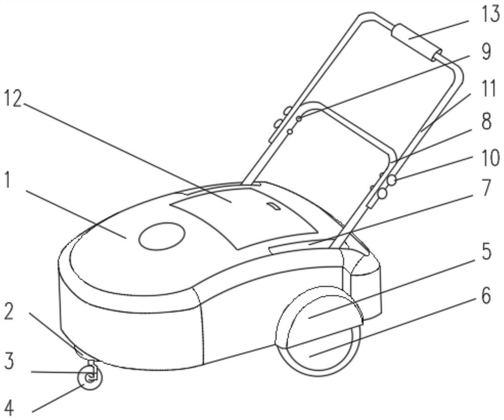
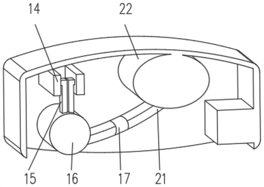
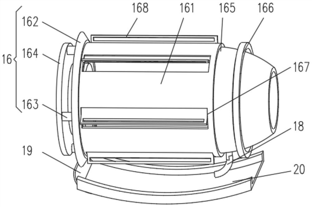
[0031] see Figure 1-3 , the present invention provides a technical solution: a garden pruning device, including a housing 1, the bottom of the housing 1 is fixedly connected with a fixed block 2, and the side of the fixed block 2 away from the housing 1 is fixedly connected with a support column 3, and the support column 3 is away from the One end of the fixed block 2 is equipped with a supporting wheel 4, and the side of the casing 1 close to the fixed block 2 is fixedly connected with a fender 5, and the side of the casing 1 close to the fender 5 is equipped with a roller 6, and the casing 1 is far away from the side of the fixed block 2. One side is symmetrically provided with a device groove 7, and the inside of the device groove 7 is connected with a push rod 8, and the end of the push rod 8 away from the device groove 7 is equipped with a connecting rod 9, and one side of the connecting rod 9 is rotated and connected with a rotating block 10, and the push rod 8 The end ...
Embodiment 2
[0038] see Figure 1-4 , the present invention provides a technical solution: on the basis of Embodiment 1, a crushing device 17 is installed on one side of the weeding device 16, and the crushing device 17 includes a bottom plate 171, and one side of the bottom plate 171 is fixedly connected with the delivery pipe 21, and the bottom plate 171 A crushing motor 172 is installed on one side, and the crushing motor 172 is connected with a sub-plate 174 through a rotating shaft 173. One end of the rotating shaft 173 runs through the sub-plate 174 and is connected with a rotating frame 175, and fan blades 176 are uniformly installed on the outside of the rotating frame 175.
[0039] One side of the bottom plate 171 is fixedly connected with a cylinder 177, and one end of the cylinder 177 away from the bottom plate 171 is equipped with a limiting plate 178, and one side of the limiting plate 178 is equipped with an air bag 179, and the air outlet of the air bag 179 is communicated wi...
Embodiment 3
[0044] see Figure 1-5 , the present invention provides a technical solution: on the basis of the second embodiment, the sliding device 15 includes a sliding frame 151, the inside of the sliding frame 151 is equipped with an elastic airbag 152, and the primary connection of the elastic airbag 152 is provided with an elastic pull ring 153, and the elastic pull One side of the ring 153 is equipped with a sliding ball 154, the sliding ball 154 is slidably connected with the sliding track 14, and the side of the elastic air bag 152 away from the elastic pull ring 153 is equipped with a hollow column 155, and the bottom of the hollow column 155 is connected with a push rod 156. An end of the rod 156 away from the hollow column 155 is fixedly connected with a push plate 157 .
[0045] During use, when the blade 168 touches a hard dead branch when weeding, the push plate 157 connected to the weeding device 16 is shaken, and the push plate 157 drives the push rod 156 to advance in the...
PUM
 Abstract
Description
Claims
Application Information
 - R&D
- Intellectual Property
- Life Sciences
- Materials
- Tech Scout
- Unparalleled Data Quality
- Higher Quality Content
- 60% Fewer Hallucinations
Browse by: Latest US Patents, China's latest patents, Technical Efficacy Thesaurus, Application Domain, Technology Topic, Popular Technical Reports.
© 2025 PatSnap. All rights reserved.Legal|Privacy policy|Modern Slavery Act Transparency Statement|Sitemap|About US| Contact US: help@patsnap.com


