Bean sprout auxiliary cultivation device
A cultivation device and technology of bean sprouts, applied in cultivation, soilless cultivation, botanical equipment and methods, etc., can solve the problems of time-consuming, laborious, low efficiency, uneven watering and other problems of bean sprouts
- Summary
- Abstract
- Description
- Claims
- Application Information
AI Technical Summary
Problems solved by technology
Method used
Image
Examples
Embodiment 1
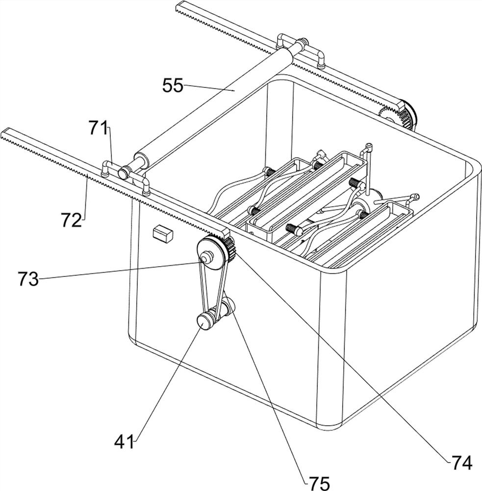
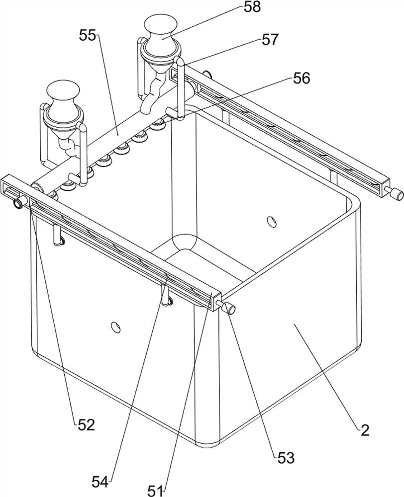
[0069] A kind of bean sprouts auxiliary cultivating device, such as figure 1 As shown, it includes a bottom plate 1, a water collection frame 2, a drain pipe 3, a material clamping mechanism 4 and a water spray mechanism 5. The inside of the water frame 2 is provided with a material clamping mechanism 4, and the upper part of the water receiving frame 2 is provided with a water spray mechanism 5.
[0070] When people cultivate bean sprouts, people put six boxes of bean sprout planting boxes in the material clamping mechanism 4, which is clamped by the material clamping mechanism 4, and then the material clamping mechanism 4 is operated, and the material clamping mechanism 4 moves the bean sprout planting boxes, and people simultaneously Pour a sufficient amount of water into the water spray mechanism 5, and make the water spray mechanism 5 run. The water spray mechanism 5 sprays water on the bean sprout planting box, and the excess water falls into the water collection frame 2...
Embodiment 2
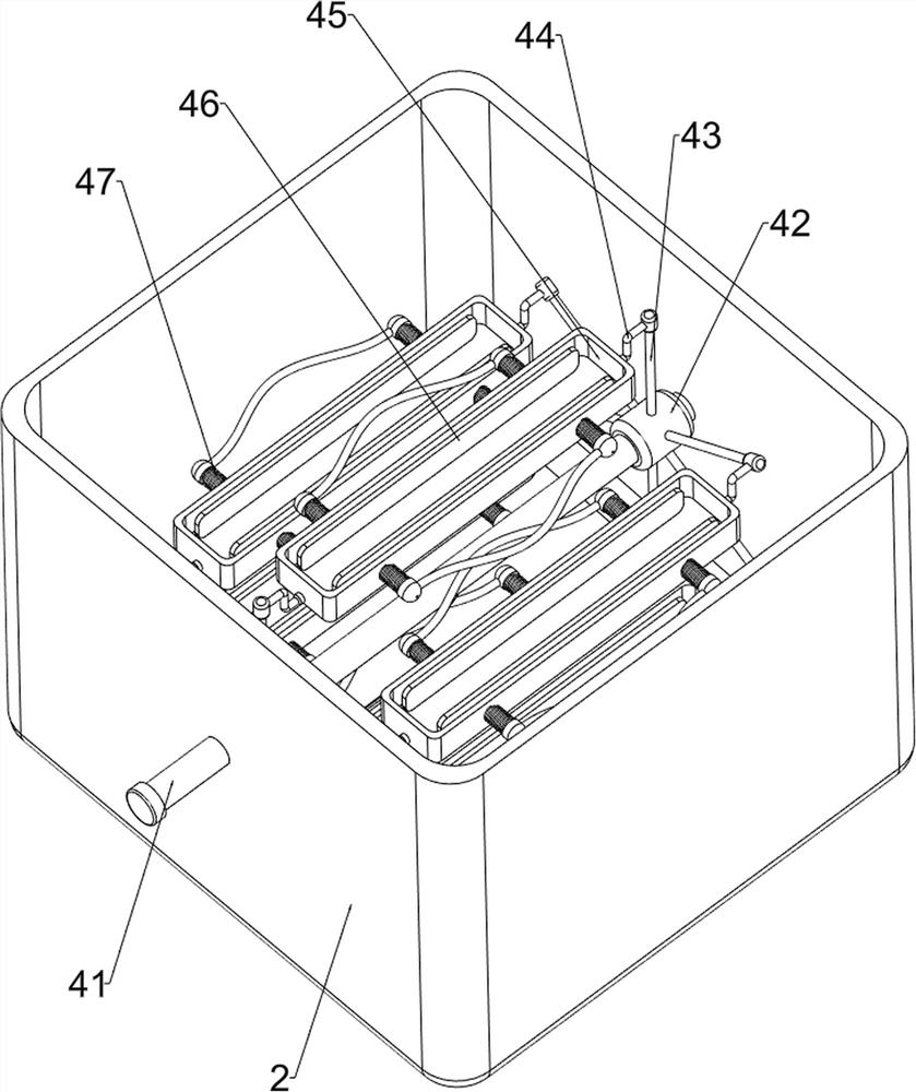
[0072] On the basis of Example 1, such as figure 2 and image 3 As shown, the clamping mechanism 4 includes a first rotating shaft 41, a mounting sleeve 42, a rotating column 43, a special-shaped column 44, a placement frame 45, a splint 46 and a first spring 47, and the water receiving frame 2 is rotated between the left and right sides. Connected with a first rotating shaft 41, the left and right sides of the first rotating shaft 41 are provided with mounting sleeves 42, and the mounting sleeves 42 on the left and right sides are provided with six rotating columns 43, and the upper part of the rotating column 43 is provided with a special-shaped column 44 in a rotating manner. A placement frame 45 is connected between the special-shaped columns 44 on the left and right sides, and the front and rear sides of the placement frame 45 are slidingly provided with splints 46, and the two splints 46 on the same placement frame 45 are wound with two first springs. 47 , the inner si...
Embodiment 3
[0077] On the basis of Example 2, such as figure 1 , Figure 4 , Figure 5 , Figure 6 and Figure 7 Shown, also comprise push mechanism 6, and push mechanism 6 includes installation block 61, air rod 62, piston rod 63 and contact block 64, and water receiving frame 2 left and right sides upper parts are all provided with two pieces of installation blocks 61, front and rear two Air rods 62 are connected between the inner sides of the mounting blocks 61 on the left and right sides, the front sides of the air rods 62 on the left and right sides are provided with piston rods 63, and the front sides of the bottoms of the first slide rods 53 on the left and right sides are provided with contact blocks 64. Block 64 cooperates with piston rod 63 .
[0078] People open the air rod 62, the operation of the air rod 62 will make the piston rod 63 move back and forth repeatedly, when the piston rod 63 moves forward, because the piston rod 63 cooperates with the contact block 64, the m...
PUM
 Abstract
Description
Claims
Application Information
 - R&D
- Intellectual Property
- Life Sciences
- Materials
- Tech Scout
- Unparalleled Data Quality
- Higher Quality Content
- 60% Fewer Hallucinations
Browse by: Latest US Patents, China's latest patents, Technical Efficacy Thesaurus, Application Domain, Technology Topic, Popular Technical Reports.
© 2025 PatSnap. All rights reserved.Legal|Privacy policy|Modern Slavery Act Transparency Statement|Sitemap|About US| Contact US: help@patsnap.com


