Supercharge Your Innovation With Domain-Expert AI Agents!

Relay type vertical conveying system and conveying method thereof

A conveying system and box conveying technology, which is applied in the field of conveyors, can solve the problems of high verticality requirements of shafts, increased conveying distance, dependence on shafts, etc., and achieve the effect of improving actual conveying capacity

Pending Publication Date: 2021-05-11
华力高科(上海)智能科技有限公司
View PDF0 Cites 3 Cited by
  • Summary
  • Abstract
  • Description
  • Claims
  • Application Information

AI Technical Summary

Problems solved by technology

[0003] Disadvantage (1): The vertical conveying efficiency of the prior art is low and cannot meet the actual conveying demand;
[0004] The reason for the disadvantage (1): Most of the newly built inpatient buildings are about 50 to 100 meters high, that is, 10 to 25 floors, and the hourly delivery demand of each vertical conveyor is 150 to 200 boxes in one direction (equivalent to 300 to 400 boxes) Two-way conveying capacity per hour (including empty container return)), and the higher the number of floors, the greater the demand for conveying efficiency
However, when the existing equipment is used in a high-rise building with about 10 floors, it only has a one-way actual conveying capacity of 60 to 70 boxes per hour, and as the number of floors increases, the actual conveying efficiency will decrease in a certain proportion. On the 25th floor, there is only a conveying efficiency of 26 to 30 cases per hour, which is far from meeting the vertical conveying and sorting needs of existing hospitals
The main reason for this defect is that the existing high-rise building flow conveying equipment (reciprocating vertical conveyor) is a serial task execution mode, that is, the next task can only be performed after one task is conveyed. When conveying materials in the vertical direction of high-rise buildings , with the increase of the floor and the increase of the lifting distance, the transportation distance will increase, and the extension of the transportation time will make the transportation efficiency of high-level materials significantly lower than that of low-level materials, which will eventually lead to a decrease in overall efficiency and cannot meet the transportation needs of hospitals. resulting in a large accumulation of tasks at the entrance of this reciprocating vertical conveyor
[0005] Disadvantage (2): the prior art relies heavily on shafts, requires high verticality of shafts, and complicated civil construction;
[0006] The cause of disadvantage (2): the vertical track of the existing equipment vertically runs through the entire shaft from top to bottom, and the rail is directly installed on the entire shaft wall. The entire shaft must be kept in a multi-point line from top to bottom to install the guide rail. Therefore, there is a serious dependence on the shaft and a high requirement for the verticality of the shaft. The existing equipment requires the plane deviation of the shaft to be less than 50mm, the cross-section of the shaft to be greater than 1500mm*1800mm, and a pit with a height of 500mm to be reserved at the bottom of the shaft for the installation of bottom anti-falling. Buffers and hooks with a load of more than 1000kg are required to be set under the roof of the hoistway for installation and maintenance of equipment
[0007] Disadvantage (3): Once the existing technology is built, it can no longer be expanded vertically up or down;
[0008] The cause of defect (3): the existing reciprocating vertical conveyor used for high-rise building transportation must run along the through shaft, the guide rail is installed on the shaft wall and runs through the entire shaft vertically, and key equipment is arranged on the top and bottom of the shaft (The motor and the hook are installed on the top of the well, and the anti-fall buffer device is arranged at the bottom of the well). The expansion is almost equivalent to rebuilding the entire well and the vertical conveyor. The cost and construction difficulty are very high, so once it is completed, it can no longer be moved vertically. expand up or down

Method used


Image

  • Relay type vertical conveying system and conveying method thereof
  • Relay type vertical conveying system and conveying method thereof
  • Relay type vertical conveying system and conveying method thereof

Examples


Embodiment 1

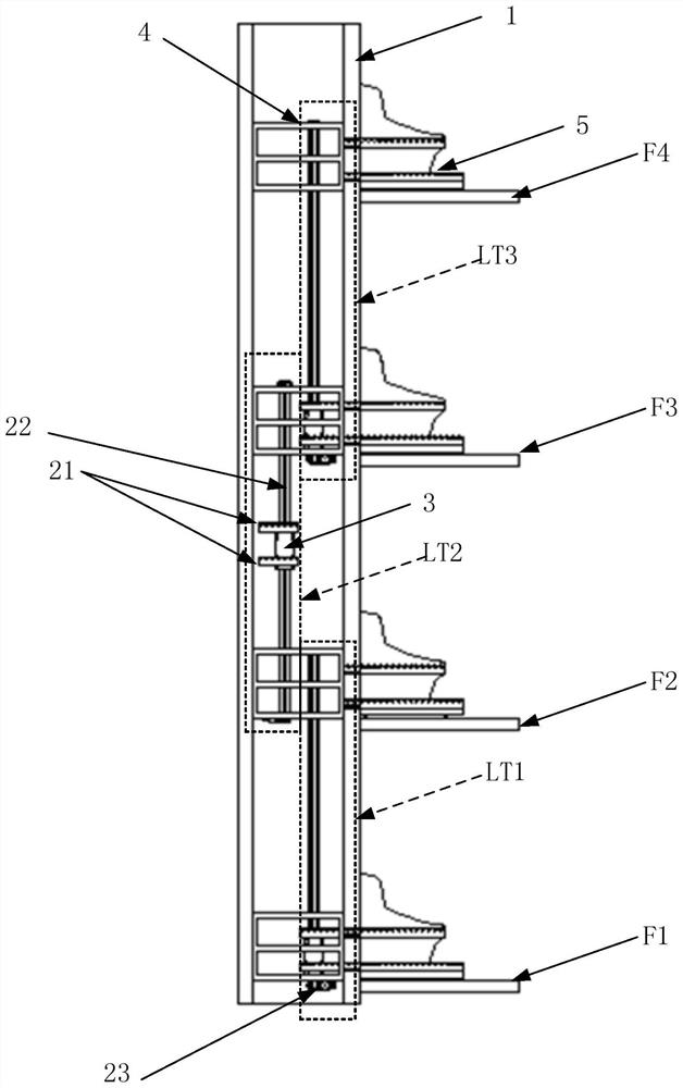
[0082] In this example, if Figure 3 to Figure 10 As shown, the task box is transported between the first floor and the sixth floor. Table 1 is the time-sequential flow chart of the relay-type vertical conveying system composed of five in-well vertical conveying modules in a six-storey building. Notes on symbols in the table: LT1, LT2, LT3, LT4, LT5 respectively represent the first to fifth in-well vertical transportation modules of the relay vertical transportation system of the present invention. F1, F2, F3, F4, F5, and F6 represent the first floor to the sixth floor respectively, and 1# box, 2# box, 3# box, 4# box, and 5# box represent 5 task boxes respectively. AT6 represents the horizontal transport module outside the well on the sixth floor.

[0083]

[0084]

[0085] Table one table two is the comparison table of the present invention and prior art:

[0086]

[0087]

[0088] Figure 11 It is a schematic diagram of the time sequence for conveying ten tas...

Embodiment 2

[0092] In this embodiment, the system of the present invention realizes simultaneous upward and downward transmission of task boxes.

[0093] At the first moment:

[0094] The slide block 3 of the vertical conveying module in the first well arrives at the first floor, and the 1# task box enters the hoistway from the first floor through the horizontal conveying module 21 in the well of the vertical conveying module in the first well; the vertical conveying module in the second and the third well Slider 3 arrives at the third floor, and the 2# task box is sent to the horizontal conveyor in the well of the vertical conveying module in the second well through the horizontal conveyor in the well of the vertical conveying module in the third well on the third floor;

[0095] At the second moment:

[0096] The sliders 3 of the vertical conveying modules in the first and second wells reach the second floor at the same time, and the vertical conveying modules in the first and second w...


PUM


Abstract

The invention provides a relay type vertical conveying system and a conveying method thereof. The system comprises a plurality of frames which are fixedly arranged in a shaft way of a vertical shaft, and each frame corresponds to one floor; several in-well vertical conveying modules which are arranged in a shaft way of the vertical shaft, and one in-well vertical conveying module is arranged between every two adjacent floors; each in-well vertical conveying module comprises a plurality of in-well horizontal conveying modules and a vertically arranged guide rail; the upper and lower ends of the guide rails are fixedly connected with two adjacent frames respectively; a first distance or a second distance is formed between the guide rails and the first side of the vertical shaft, and different distances are formed between the adjacent guide rails and the first side of the vertical shaft; the in-well horizontal conveying module is located in the vertical shaft and is slidably arranged on the corresponding guide rail and is used for bearing and horizontally conveying a task box in the direction facing / back to the first side of the vertical shaft; and several out-well horizontal conveying modules corresponding to the positions of the vertical shaft mouths are further arranged in the building floors.

Description

technical field [0001] The invention relates to a conveyor, in particular to a relay type vertical conveying system and a conveying method thereof. Background technique [0002] The high-rise building flow conveying equipment (reciprocating vertical conveyor) of the existing hospital box-type logistics conveying system adopts the reciprocating conveying method of the car, and its working principle is similar to that of an elevator, that is, a vertically connected shaft is used between each floor. A vertical guide rail is installed, on which a car that can move vertically is hung, and entrances and exits are set on each floor according to requirements. When working, the entrance station sends a conveying request, and the vertical conveyor car responds and stays at the entrance station. The material is transported from the entrance station to the car of the vertical conveyor. The vertical movement of the vertical conveyor transports the materials to the destination floor, an...

Claims


Application Information

Patent Timeline
IPC IPC(8): B66B9/00B66B11/00B66B7/02
CPCB66B9/003B66B11/006B66B7/02
Inventor 陆峰孙利堂张伟朱镇鸿
Owner 华力高科(上海)智能科技有限公司
Features
  • R&D
  • Intellectual Property
  • Life Sciences
  • Materials
  • Tech Scout
  • Unparalleled Data Quality
  • Higher Quality Content
  • 60% Fewer Hallucinations
Learn More