A composite high-speed intake and exhaust valve

An intake and exhaust valve, compound technology, applied in the direction of lift valve, valve details, valve device, etc., can solve the problem of poor durability of compound high-speed intake and exhaust valve, and achieve improved operation stability, work stability, and durability. sexual effect

Active Publication Date: 2022-05-06
SHANGHAI HUHANG VALVE CO LTD
View PDF7 Cites 0 Cited by
  • Summary
  • Abstract
  • Description
  • Claims
  • Application Information

AI Technical Summary

Problems solved by technology

[0004] Therefore, in view of the above-mentioned problems, the present invention provides a composite high-speed intake and exhaust valve, which mainly solves the problem of poor durability of the composite high-speed intake and exhaust valve in the prior art

Method used


Image

  • A composite high-speed intake and exhaust valve
  • A composite high-speed intake and exhaust valve
  • A composite high-speed intake and exhaust valve

Examples


Embodiment Construction

[0023] The present invention will be further described in conjunction with the accompanying drawings and specific embodiments.

[0024] Embodiments of the invention are:

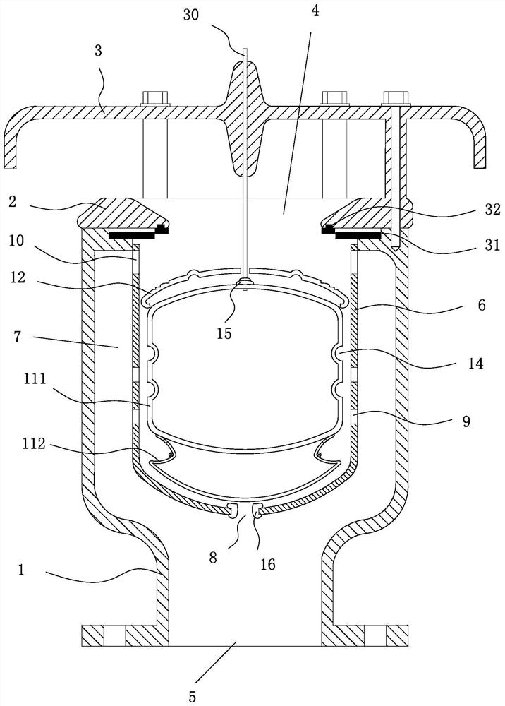
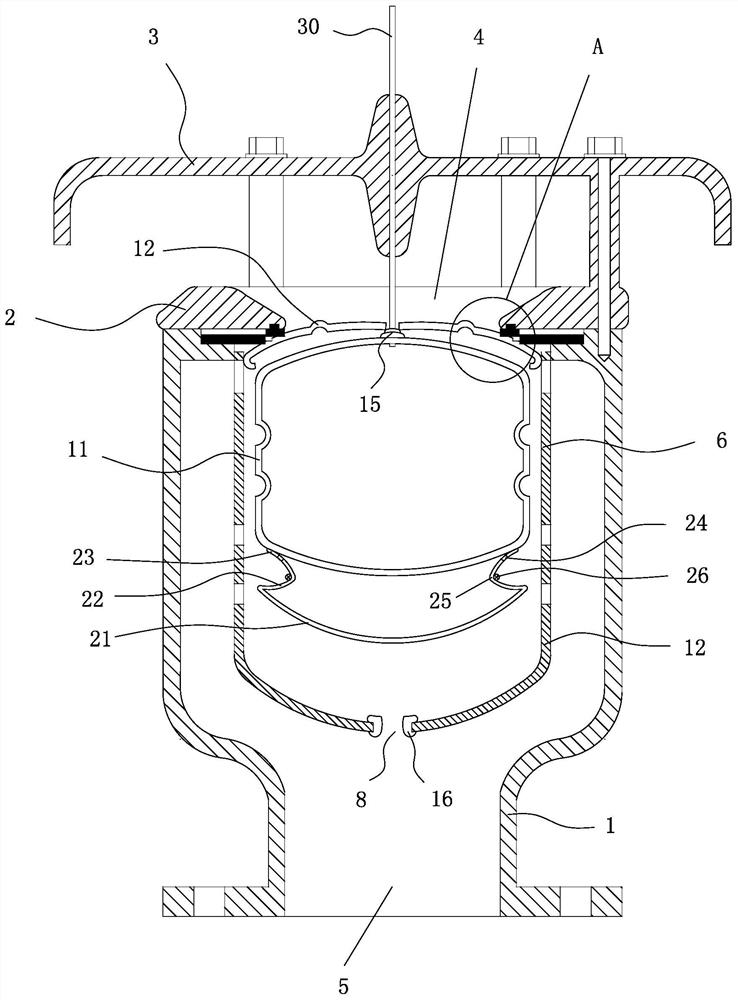
[0025] refer to figure 1 and figure 2 As shown, a compound high-speed intake and exhaust valve includes a valve body 1, a valve cover 2 arranged on the valve body 1, an exhaust cover 3 arranged on the upper side of the valve cover 2, and the valve cover 2 is provided with Intake and exhaust ports 4, the ratio of the diameter of the intake and exhaust ports 4 to the outer diameter of the valve cover 2 is 4:5, the valve body 1 is provided with an inner cavity and an inlet 5 communicating with the inner cavity, The middle part of the inner cavity is provided with a floating body cover 6, through which a flow channel 7 is formed between the valve body 1 and the floating body cover 6, and the bottom, side wall and upper part of the floating body cover 6 are respectively provided with a floating body cover 6 I...


PUM


Abstract

The invention relates to a composite high-speed intake and exhaust valve, which mainly solves the problem of poor durability of the composite high-speed intake and exhaust valve in the prior art, including a valve body, a valve cover, and an exhaust cover. There are inlet and exhaust ports, the valve body is provided with an inner cavity and an inlet connected to the inner cavity, a floating body cover is provided in the middle of the inner cavity, and the bottom and upper parts of the floating body cover are respectively provided with a floating body cover. The first through hole and the second through hole of the flow channel, the floating body cover is provided with a floating body and a lifting cover, the lifting cover is distributed on the upper side of the floating body, and a third through hole is provided in the middle, the floating body The upper part of the valve rod is provided with a valve rod, which passes through the third through hole and is connected with the exhaust cover, and the valve rod is in clearance fit with the third through hole, and the valve rod is provided with a sealing ring.

Description

technical field [0001] The invention relates to a composite high-speed intake and exhaust valve. Background technique [0002] The composite high-speed intake and exhaust valve is a special intake and exhaust control device for water supply and drainage pipes, which is widely used in various water plants and pipe network systems in various water supply fields. Since the intake and exhaust valves are often installed at a higher position in the pipeline system, their purpose is to facilitate intake and exhaust. When a large amount of air is generated in the pipeline, the air will continue to flow to high places. The pipe is at a high place and is in an open state. A large amount of air will be blown into the bottom of the intake and exhaust valve from the pipe, and will be discharged from the exhaust port of the intake and exhaust valve after passing through the inner cavity of the valve. , because the pressure of the outside atmospheric pressure is higher than the pressure i...

Claims


Application Information

Patent Timeline
Patent Type & Authority Patents(China)
IPC IPC(8): F16K31/20F16K33/00F16K1/36F16K1/46F16K47/00
CPCF16K31/20F16K33/00F16K1/36F16K1/46F16K47/00
Inventor 陈思良谢洪文张书恩卢爱山
Owner SHANGHAI HUHANG VALVE CO LTD
Why Eureka
Try Eureka