Air conditioning system and control method thereof

An air-conditioning system and cylinder technology, which is applied in the direction of air-conditioning systems, refrigerators, heating methods, etc., can solve the problems of high oil output rate of compressors, lower energy efficiency of air-conditioning systems, and lower flow rate, so as to improve energy efficiency, high efficiency, and energy efficiency improvement Effect

Active Publication Date: 2022-07-12
SHANGHAI HITACHI ELECTRICAL APPLIANCES CO LTD
View PDF7 Cites 0 Cited by
  • Summary
  • Abstract
  • Description
  • Claims
  • Application Information

AI Technical Summary

Problems solved by technology

[0004] However, during the exhaust process of the above-mentioned compressor, the refrigerant compressed by the first cylinder and the second cylinder is discharged from the same exhaust port. When the refrigerant leaves the cylinder, it will carry liquid oil droplets and flow upward. When the upper cavity of the machine housing is used, the flow rate decreases and the ability of the refrigerant to carry oil droplets decreases
At the same time, due to the effects of oil baffles, motors and other components, some oil droplets will eventually fall into the oil pool at the bottom of the compressor, but there are still a large number of oil droplets that will leave the compressor from the above-mentioned exhaust port with the refrigerant. The oil output rate of the compressor is very high, which affects its practical application
When the compressor is directly applied to the air-conditioning system, the lubricating oil inside the compressor will enter the system as the exhaust port leaves the oil pool at the bottom of the compressor, and adhere to the evaporator, condenser and system piping, thus Reduced energy efficiency of air conditioning systems
At the same time, it will also lead to increased wear and stuck inside the compressor due to lack of oil.

Method used


Image

  • Air conditioning system and control method thereof
  • Air conditioning system and control method thereof
  • Air conditioning system and control method thereof

Examples


Embodiment Construction

[0074] Example embodiments will now be described more fully with reference to the accompanying drawings. Example embodiments, however, can be embodied in various forms and should not be construed as limited to the embodiments set forth herein. Rather, these embodiments are provided so that this disclosure will be thorough and complete, and will fully convey the concept of example embodiments to those skilled in the art. The same reference numerals in the drawings denote the same or similar structures, and thus their repeated descriptions will be omitted.

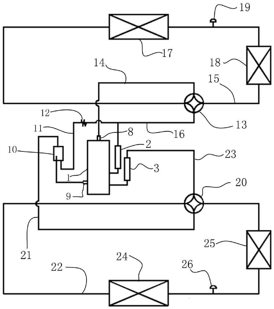
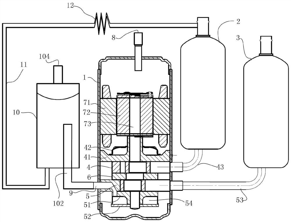
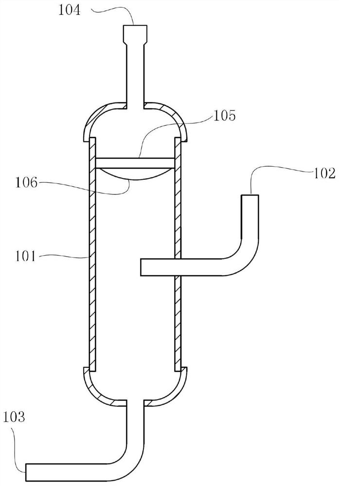
[0075] figure 1 It is a schematic diagram of the structure of the air conditioning system of the present invention. figure 2 It is a schematic diagram of the structure of the compressor in the present invention. image 3 It is a schematic structural diagram of an oil separator in an embodiment of the present invention. as well as Figure 4 It is a schematic structural diagram of an oil separator in another embodiment o...


PUM


Abstract

The invention discloses an air-conditioning system and a control method thereof. The air-conditioning system comprises: a compressor, including a casing, a first liquid accumulator, a second liquid accumulator, a first cylinder and a second cylinder; the first A cylinder and a second cylinder are arranged in the casing; the first cylinder is connected to the air outlet of the first liquid reservoir through a first suction pipe, and the second cylinder is connected through a second suction pipe the air outlet of the second accumulator; the compressor discharges the refrigerant compressed by the first cylinder and the refrigerant compressed by the second cylinder through a first exhaust port and a second exhaust port respectively an oil separator, the oil separator is provided with a first air inlet, a third air outlet and a first oil outlet; the first air inlet is connected to the second air outlet. The present invention can improve the energy efficiency of the air-conditioning system and at the same time reduce the oil output rate of the compressor, so that the air-conditioning system can run stably.

Description

technical field [0001] The invention relates to the field of refrigeration equipment, in particular to an air conditioning system and a control method thereof. Background technique [0002] Chinese patent application (publication number: CN109405330A) discloses a compressor and a heat pump system, the compressor includes: a compressor body, the compressor body is provided with a first air inlet, a second air inlet and an air outlet, The compressor body is provided with a first cylinder and a second cylinder, the first air inlet is communicated with the air inlet of the first cylinder, the second air inlet is communicated with the air inlet of the second cylinder, the first air cylinder and the second air cylinder are connected to each other. The air outlets of the cylinders are all communicated with the exhaust ports. The heat pump system uses the above-mentioned compressor to achieve the purpose of improving the energy efficiency of the heat pump system. The heat pump sys...

Claims


Application Information

Patent Timeline
Patent Type & Authority Patents(China)
IPC IPC(8): F24F5/00F25B43/00F25B43/02F25B13/00F25B41/31
CPCF24F5/0003F25B43/006F25B43/02F25B13/00
Inventor 张利王瑞雄
Owner SHANGHAI HITACHI ELECTRICAL APPLIANCES CO LTD
Why Eureka
Try Eureka