Capturing net

A net cover and handle technology, applied in the field of capture, can solve problems such as inability to control quickly, and achieve the effects of simple structure, convenient use, and short capture time.

Pending Publication Date: 2021-05-11
青海宇航通信科技有限公司
View PDF6 Cites 0 Cited by
  • Summary
  • Abstract
  • Description
  • Claims
  • Application Information

AI Technical Summary

Problems solved by technology

[0004] The purpose of the present invention is to provide a catching net to solve the dilemma that relevant workers cannot quickly control it when they encounter special situations in their work

Method used


Image

  • Capturing net
  • Capturing net
  • Capturing net

Examples


Embodiment 1

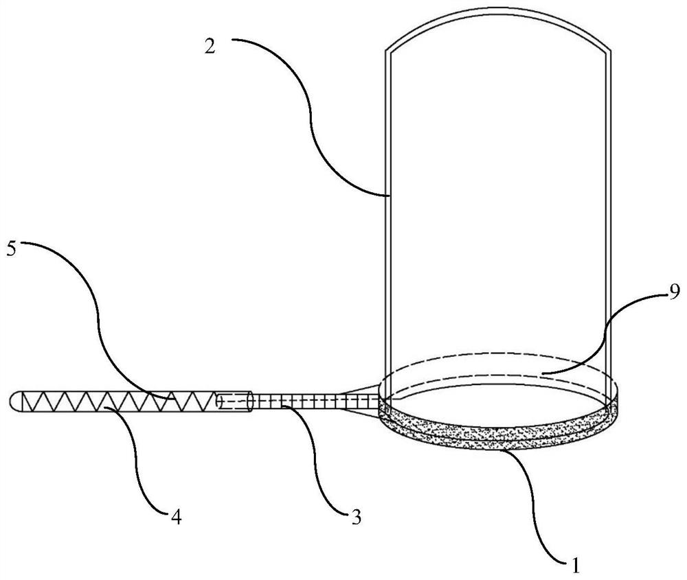
[0037] The catch net includes: a support ring 1, a handle, and a net cover 2; the inner side of the support ring 1 is provided with a net cover 2; the outer cover is detachably linked with the support ring 1; the outer side of the support ring 1 is connected with Handle; said handle telescoping handle.

[0038] The handle is divided into a front end and a rear end; the front end is sleeved on the rear end; the front end is hollow, and a rack tubular structure is arranged on the surface; the rear end is a hollow tube; There is a spring 5; the end of the handle away from the support ring 1 is closed.

Embodiment 2

[0040] The catching net includes: a support ring 1, a handle, and a net cover 2; the inside of the support ring 1 is provided with a net cover 2; the net cover 2 is detachably linked to the support ring 1;

[0041] The outer side of the support ring 1 is connected with a handle; the handle is a telescopic handle;

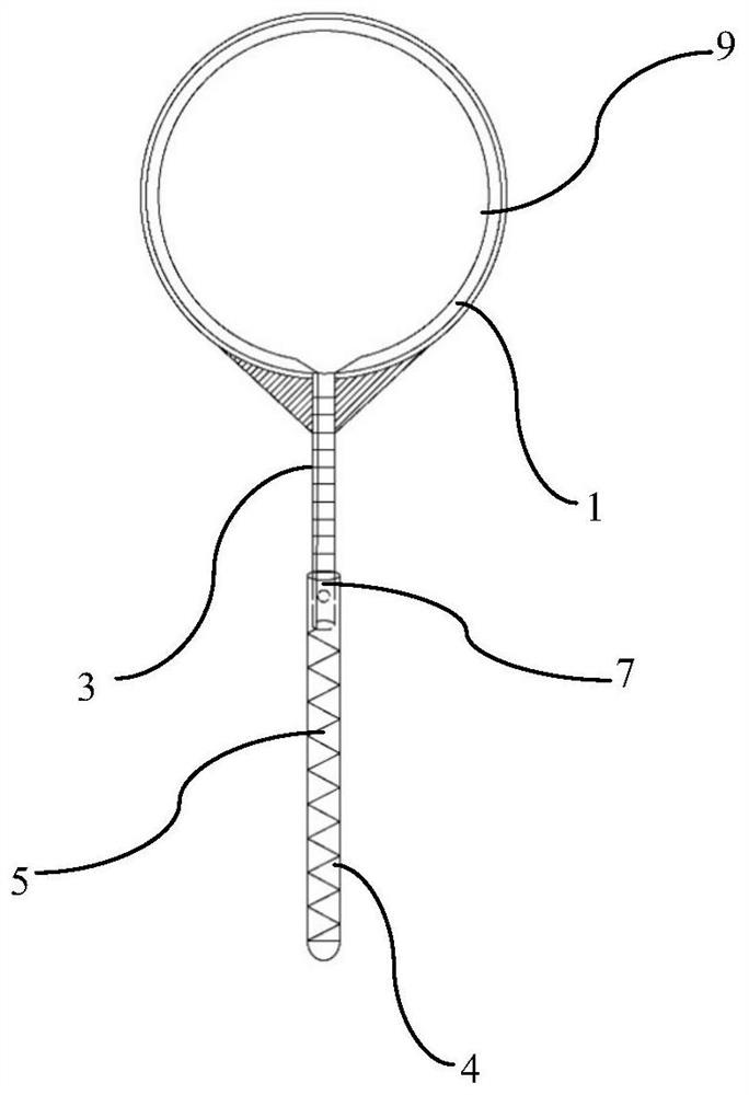
[0042] The handle is divided into a front handle 3 and a rear handle 4; the front handle 3 and the rear handle 4 are hollow tubes; the front handle 3 is set on the rear handle 4; the rear handle 4 is provided with a spring 5;

[0043] The end of the handle away from the support ring 1 is closed;

[0044] The end of the rear handle 4 away from the closed end is provided with a buckle button 7 .

[0045] The support ring 1 is composed of two semicircles, the semicircle joint is provided with a circular shaft, and the semicircle joint is provided with buckles; after the support ring composed of the two semicircles is unfolded, the semicircle joint is stuck The role ...

Embodiment 3

[0049] The catch net, the catch net includes: a support ring 1, a handle, and a net cover 2; the inside of the support ring 1 is provided with a net cover 2; the net cover 2 and the support ring 1 are detachably linked;

[0050] The outer side of the support ring 1 is connected with a handle; the handle is a telescopic handle;

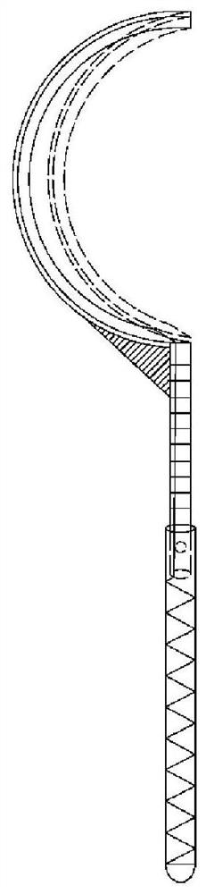
[0051] The handle is divided into a front handle 3 and a rear handle 4; the front handle 3 is set on the rear handle 4; the front handle 3 is hollow, and a rack is provided on the surface; the rear handle 4 is A hollow tube; the hollow tube is provided with a spring 5; the end of the handle away from the support ring 1 is closed; the front handle 3 is detachably connected to the support ring 1.

[0052] A reinforcing block is provided at the joint between the support ring and the front handle 3;

[0053] The end of the rear handle 4 away from the closed end is provided with a buckle button 7 .

[0054] The support ring 1 is provided with a steel wire...


PUM


Abstract

The invention relates to the technical field of capturing, in particular to a capturing net. The capturing net comprises a supporting ring, a handle and a net cover; the net cover is arranged on the inner side of the supporting ring; the net cover is detachably connected with the supporting ring; the outer side of the supporting ring is connected with the handle; the handle is a telescopic handle; the handle is divided into a front-end handle and a rear-end handle; the front-end handle is sleeved on the rear-end handle; the front-end handle is hollow, and a movable rack is arranged in the front-end handle and is connected with a steel wire; the rear-end handle is a hollow tube; a spring is arranged in the hollow pipe and is connected with a rack in the front-end handle; and the end, away from the supporting ring, of the handle is closed. The device has the advantages of being simple in structure and convenient to manufacture and use; the capturing effect is good, safe and reliable; the capturing time is short, and the disposal speed is high; and the applicability is wide.

Description

technical field [0001] The invention relates to the technical field of capture, in particular to a capture net. [0002] technical background [0003] a catch net Contents of the invention [0004] The object of the present invention is to provide a catching net to solve the dilemma that relevant workers cannot quickly control it when they encounter special situations in their work. [0005] The catching net includes: a support ring 1, a handle, and a net cover 2; the inside of the support ring 1 is provided with a net cover 2; the net cover 2 is detachably linked with the support ring 1; [0006] The outer side of the support ring 1 is connected with a handle; the handle is a telescopic handle; [0007] The handle is divided into a front handle 3 and a rear handle 4; the front handle 3 and the rear handle 4 are hollow tubes; the front handle 3 is set on the rear handle 4; the rear handle 4 is provided with a spring 5; [0008] The end of the handle away from the suppor...

Claims


Application Information

Patent Timeline
Patent Type & Authority Applications(China)
IPC IPC(8): F41B15/00
CPCF41B15/00
Inventor 马建华
Owner 青海宇航通信科技有限公司
Why Eureka
Try Eureka