Bending test device and method applied to radio frequency coaxial cable assembly
A radio frequency coaxial cable, bending test technology, applied in the measurement device, the use of repetitive force/pulse force to test the strength of materials, instruments and other directions, can solve the problem of affecting the accuracy of cable bending test and so on
- Summary
- Abstract
- Description
- Claims
- Application Information
AI Technical Summary
Problems solved by technology
Method used
Image
Examples
Embodiment 1
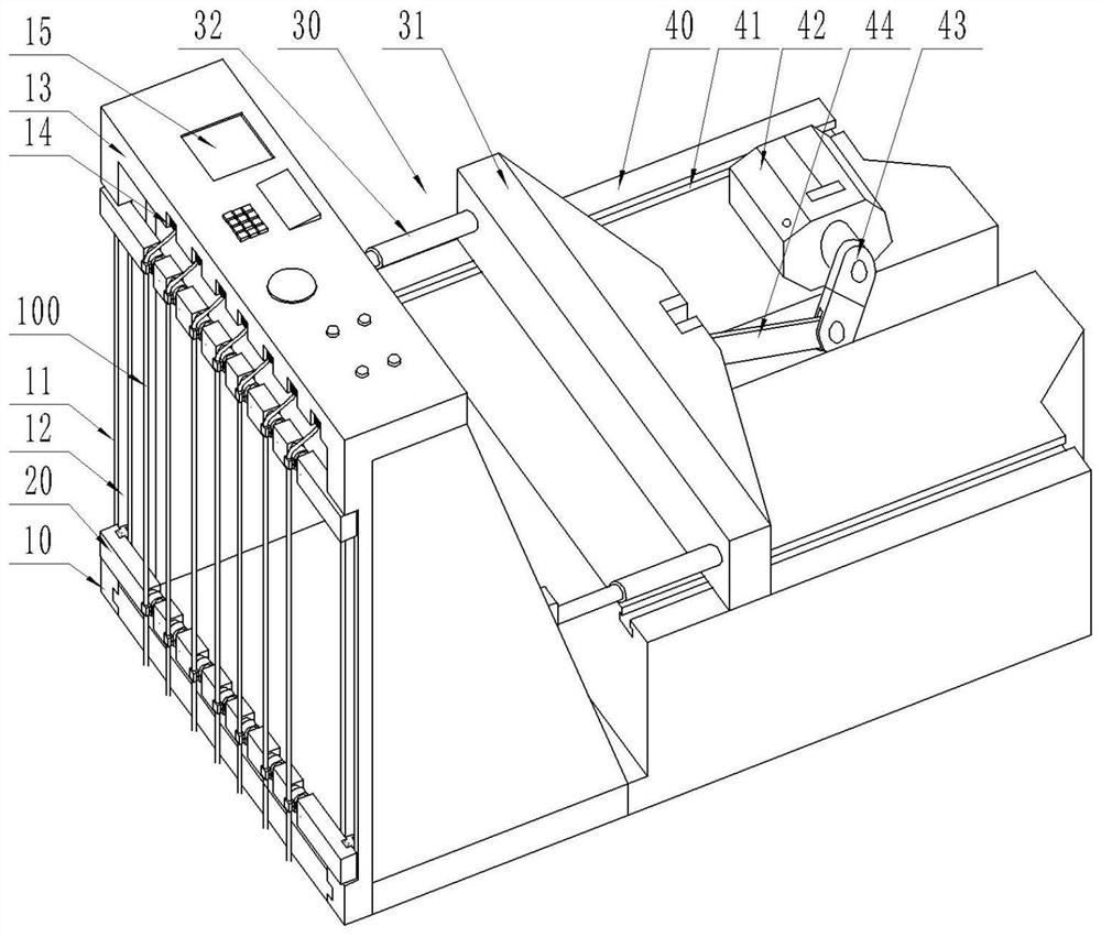
[0068] A bending test device applied to radio frequency coaxial cable assemblies, wherein, such as figure 1 As shown, it includes: a supporting rail part 10 , a movable clamping beam 20 , a transmission mechanism 30 , a mounting table 40 , a driving motor 42 , and an eccentric rotating rod 43 .
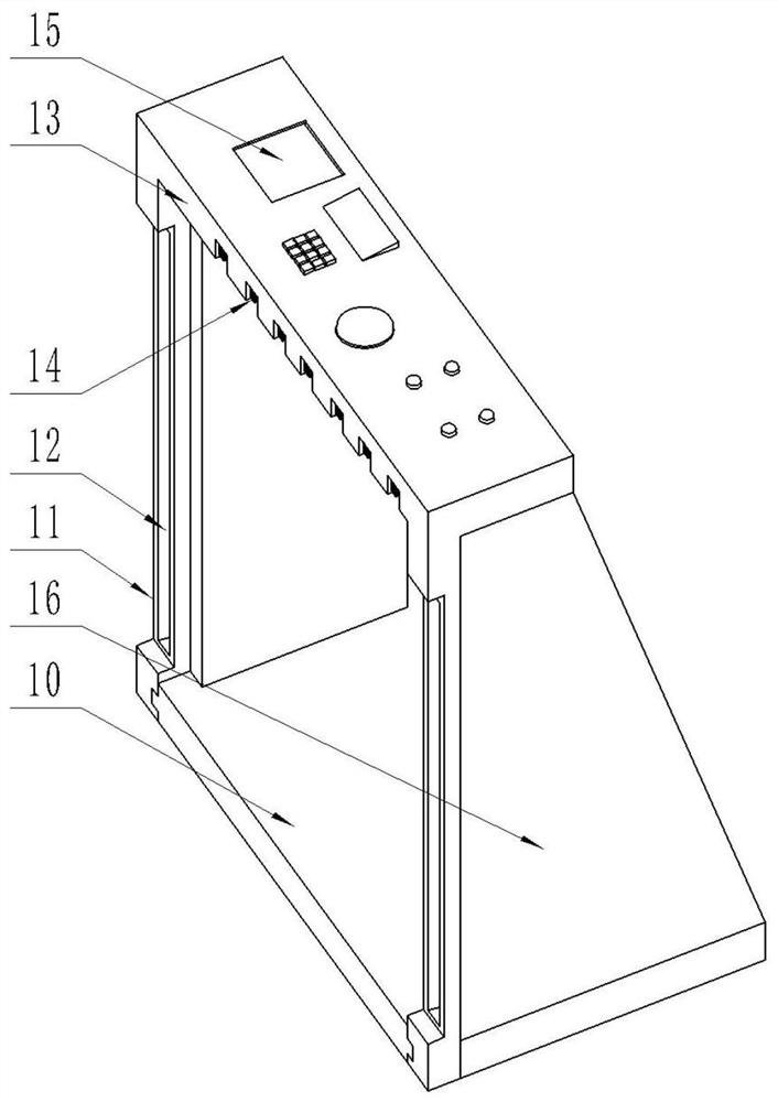
[0069] like figure 1 , 2 As shown, the supporting rail part 10 has a supporting element 11 , and a rail groove 12 is arranged on the supporting element 11 .
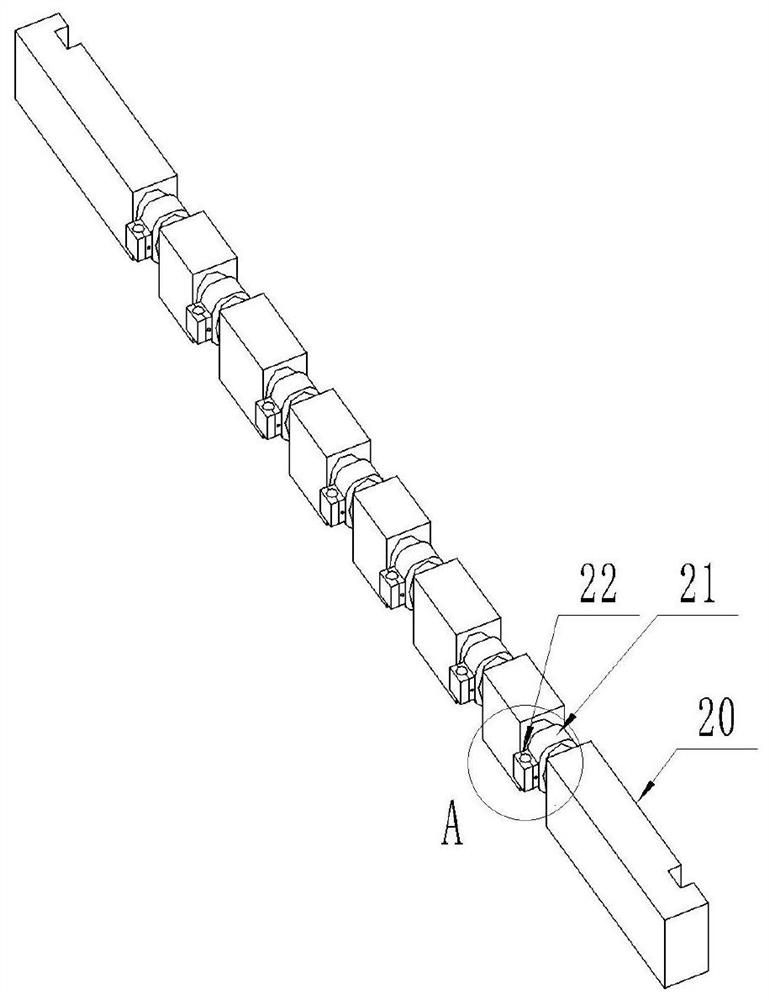
[0070] like figure 1 , 3 , 4, the movable clamp beam 20 is slidingly connected with the track groove 12 of the support element 11, the movable clamp beam 20 is distributed at both ends of the support element 11, the movable clamp beam 20 has a rotating part 21 and a line clamp head 22, the line clamp The head 22 is fixedly installed on the rotating part 21, and there is an elastic elastic part between the two. The wire clamp head 22 has a through wire hole 23. The radio frequency coaxial cable assembly 100 is arranged betwee...
Embodiment 2
[0084] A bending test device applied to a radio frequency coaxial cable assembly has the same characteristic structure as that of Embodiment 1, wherein, such as Figure 4 , 7 As shown, the collet is formed by laminating the first clamping part 221 and the second clamping part 222. The second clamping part 222 has a limit rod 24 extending into the first clamping part 221. The limit rod 24 The first clamping portion 221 is telescopically connected, and a return spring 25 is provided between the limiting rod 24 and the first clamping portion 221 .
[0085] like Figure 7 , 8 As shown, the end of the limiting rod 24 extending into the first clamping portion 221 has a locking head 26 , and both sides of the locking head 26 have lock openings.
[0086] The first clamping portion 221 is provided with an unlocking button 27 and a lateral sliding platform 28 , the first clamping portion 221 is connected with the lateral sliding platform 28 , and the unlocking button 27 is connected ...
Embodiment 3
[0092] A bending test method applied to a radio frequency coaxial cable assembly, comprising the following steps:
[0093] After the radio frequency coaxial cable assembly 100 passes through the line hole 23 of the clamp, the radio frequency coaxial cable assembly 100 is fixed on the movable clamp beam 20 by the clamp, and then the high frequency plugs at both ends of the radio frequency coaxial cable assembly 100 Inserted on the high-frequency socket 14 on the bottom of the upper top plate 13 and on the high-frequency socket 14 of the support track portion 10, so that the detection circuit in the radio frequency coaxial cable assembly 100 and the operating system 15 is conducted, and the radio frequency coaxial cable assembly When bending 100 times repeatedly, according to the relationship between the bending rate and time set in the test, it is automatically converted into the number of bending times, and the number of bending tests is counted to ensure real-time monitoring a...
PUM
 Abstract
Description
Claims
Application Information
 - R&D
- Intellectual Property
- Life Sciences
- Materials
- Tech Scout
- Unparalleled Data Quality
- Higher Quality Content
- 60% Fewer Hallucinations
Browse by: Latest US Patents, China's latest patents, Technical Efficacy Thesaurus, Application Domain, Technology Topic, Popular Technical Reports.
© 2025 PatSnap. All rights reserved.Legal|Privacy policy|Modern Slavery Act Transparency Statement|Sitemap|About US| Contact US: help@patsnap.com


