
Structured light projection device

A projection device and structured light technology, applied in the direction of measuring devices, optics, optical components, etc., can solve the problems of increasing structure and volume, increasing optical path distance, inconvenience, miniaturization, miniaturization design, etc., to achieve portability, Increase the optical path and achieve the effect of miniaturization

Active Publication Date: 2022-06-24
TRIPLE WIN TECHSHENZHEN CO LTD
View PDF13 Cites 0 Cited by
  • Summary
  • Abstract
  • Description
  • Claims
  • Application Information

AI Technical Summary

Problems solved by technology

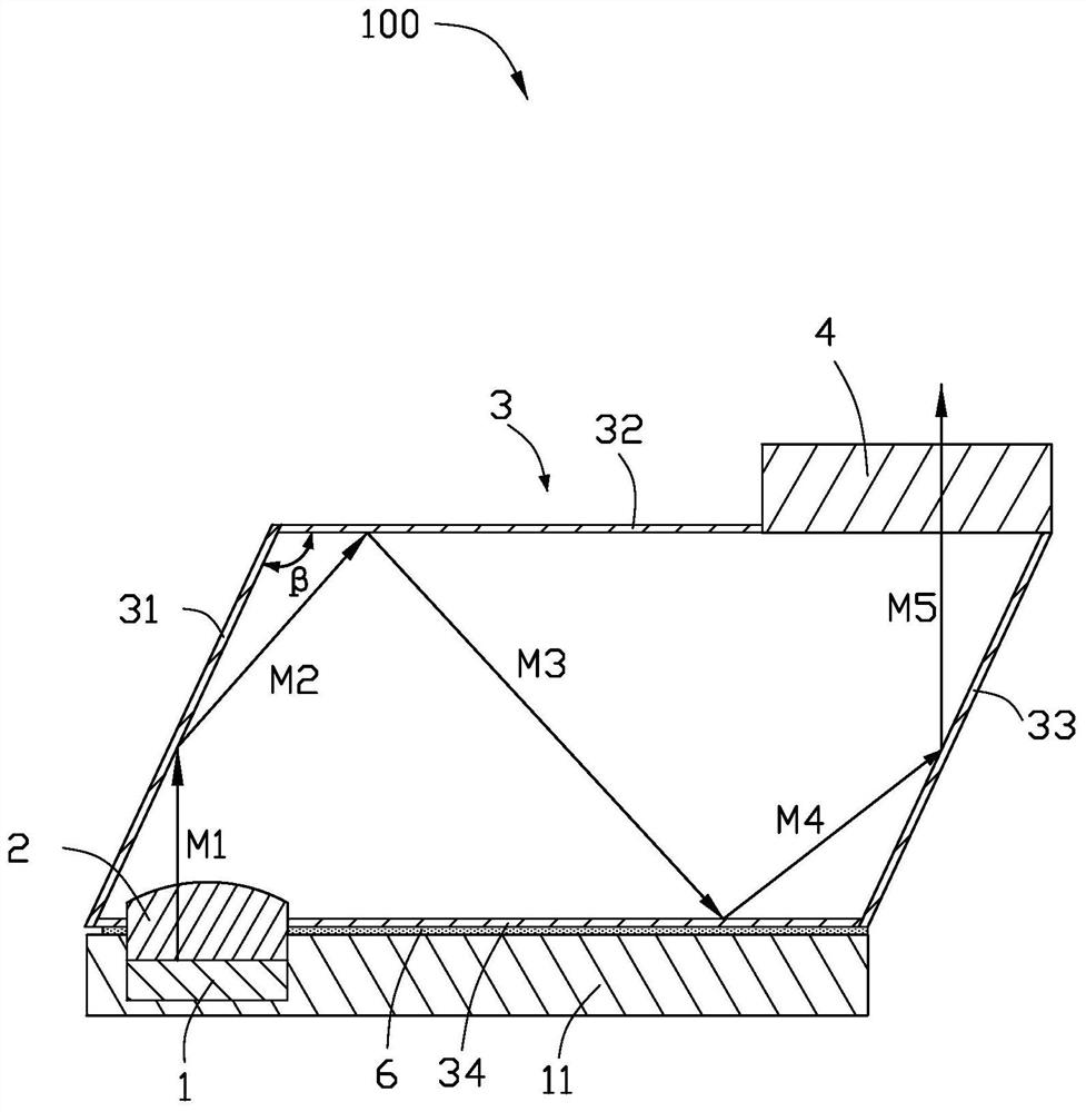
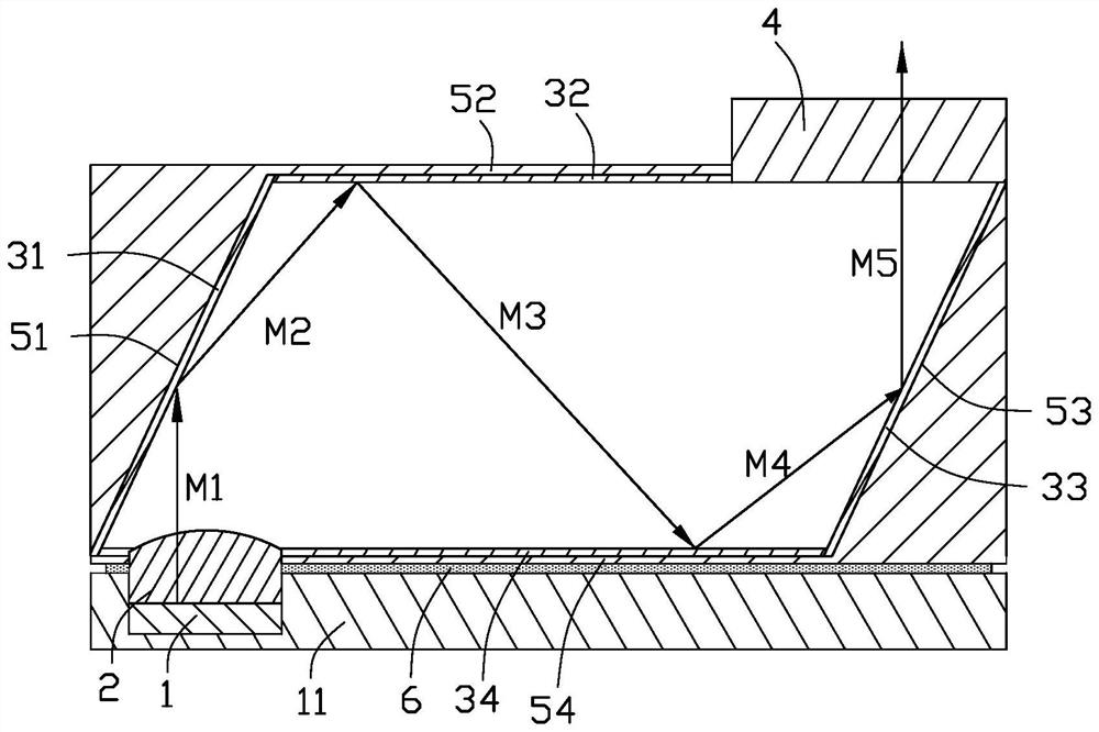
When the light source is emitted, the light spot can be optimized through a certain distance of optical path; however, in order to increase the optical path distance, the structure and volume of the product will be correspondingly increased, which is not convenient for lightweight and miniaturized design

Method used


Image

  • Structured light projection device
  • Structured light projection device
  • Structured light projection device

Examples


Embodiment Construction

[0028] In order to more clearly understand the above objects, features and advantages of the present invention, the present invention will be described in detail below with reference to the accompanying drawings and specific embodiments. It should be noted that the embodiments of the present application and the features in the embodiments may be combined with each other in the case of no conflict.

[0029] In the following description, many specific details are set forth in order to facilitate a full understanding of the present invention, and the described embodiments are only some, but not all, embodiments of the present invention. Based on the embodiments of the present invention, all other embodiments obtained by those of ordinary skill in the art without creative efforts shall fall within the protection scope of the present invention.

[0030] Unless otherwise defined, all technical and scientific terms used herein have the same meaning as commonly understood by one of or...


PUM


Abstract

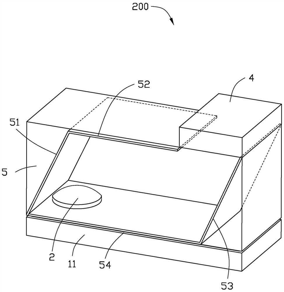
The present invention provides a structured light projection device, which includes: a light source for emitting laser light; an optical path changing element arranged on the outgoing light path of the laser light, and the optical path changing element is used for changing the propagation direction of the laser light; and A diffractive optical element arranged on the changed optical path of the laser light, the diffractive optical element is used to generate structured light; it is characterized in that: the optical path changing element can change the propagation direction of the laser light at least three times and after the last change The emitting direction of the laser light following the propagating direction is parallel to the emitting direction from the light source.

Description

technical field [0001] The present invention relates to the technical field of depth cameras, and more particularly, to a structured light projection device for depth cameras. Background technique [0002] This section is intended to provide a background or context for the specific embodiments of the invention that are recited in the claims. The descriptions herein are not admitted to be prior art by inclusion in this section. [0003] The depth camera can obtain the depth information of the target to realize 3D scanning, scene modeling, and gesture interaction. Compared with the currently widely used RGB camera, the depth camera is gradually being valued by all walks of life. For example, the combination of a depth camera, a TV, a computer, etc., can realize a somatosensory game to achieve the effect of two-in-one game and fitness. [0004] The core component of the depth camera is the optical projection module. With the continuous expansion of applications, the optical p...

Claims


Application Information

Patent Timeline
Patent Type & Authority Patents(China)
IPC IPC(8): G03B15/05G02B27/42G02B17/02G02B17/06
CPCG03B15/05G02B27/4205G02B17/023G02B17/06G02B27/425G02B17/006G01C3/02G02B27/30
Inventor 齐伟伟林精皇
Owner TRIPLE WIN TECHSHENZHEN CO LTD
Learn More