
Unmanned aerial vehicle tilt turning method adopting non-minimum phase corrector

An unmanned aerial vehicle, non-minimum phase technology, which is applied in the direction of instruments, non-electric variable control, three-dimensional position/course control, etc., can solve the problem of reverse movement in the initial stage of unmanned aerial vehicle tilting and turning, so as to reduce the cost of measurement and reduce the volume effect

Active Publication Date: 2020-12-04
NAVAL AVIATION UNIV
View PDF7 Cites 2 Cited by
  • Summary
  • Abstract
  • Description
  • Claims
  • Application Information

AI Technical Summary

Problems solved by technology

[0004] The object of the present invention is to provide a method of tilting and turning an unmanned aerial vehicle using a non-minimum phase corrector, and then at least to a certain extent overcome the problem of the reverse motion of the initial section of the tilting and turning of the unmanned aerial vehicle caused by the limitations and defects of the related technology question

Method used


Image

  • Unmanned aerial vehicle tilt turning method adopting non-minimum phase corrector
  • Unmanned aerial vehicle tilt turning method adopting non-minimum phase corrector
  • Unmanned aerial vehicle tilt turning method adopting non-minimum phase corrector

Examples


Embodiment Construction

[0063] Example embodiments will now be described more fully with reference to the accompanying drawings. Example embodiments may, however, be embodied in many forms and should not be construed as limited to the examples set forth herein; rather, these embodiments are provided so that this disclosure will be thorough and complete and fully convey the concept of example embodiments to those skilled in the art. The described features, structures, or characteristics may be combined in any suitable manner in one or more embodiments. In the following description, numerous specific details are provided in order to give a thorough understanding of embodiments of the invention. However, those skilled in the art will appreciate that the technical solution of the present invention may be practiced without one or more of the specific details, or other methods, components, devices, steps, etc. may be adopted. In other instances, well-known technical solutions have not been shown or descr...


PUM


Abstract

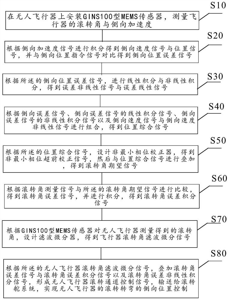
The invention relates to an unmanned aerial vehicle tilt turning method adopting a non-minimum phase corrector. Firstly, an expected mass center position signal of lateral movement is set according toa flight mission, a GINS100 type MEMS sensor is installed, the roll angle and the lateral acceleration of the aircraft are measured, and a lateral speed and a position signal are obtained through integration. A position error signal, an integral signal and a speed signal are superposed to obtain a position comprehensive signal, a non-minimum phase corrector is designed to obtain a roll angle expected signal, the roll angle expected signal is compared with a roll angle measurement signal to obtain a roll angle error signal, and non-linear integration and filtering differential calculation is carried out to form a comprehensive control signal of a roll channel, and tilt turning of the unmanned aerial vehicle is achieved in the uncontrolled state of a yawing channel. The method has the advantages that the non-minimum phase reverse motion characteristic of lateral motion is eliminated, so that the turning has good dynamic performance.

Description

technical field [0001] The invention relates to the field of center-of-mass control of unmanned aerial vehicles, in particular to a method for tilting and turning of unmanned aerial vehicles using a non-minimum phase corrector. Background technique [0002] The lateral center of mass control of an aircraft, whether it is a manned aircraft, such as an aircraft, a fighter, or an unmanned aircraft, is currently widely used in two ways: sideslip turn and bank turn. The sideslip turn is realized through the control of the yaw channel, and the roll channel is basically uncontrolled, just keep stable. The banked turn can realize the turn by controlling the roll angle of the roll channel, and at the same time, the yaw channel is free to fly without control. Comparing the two techniques, sideslip turns are more stable but less maneuverable, while banked turns are quicker but less stable than sideslip turns. However, some unmanned aerial vehicles have relatively obvious non-minimum ...

Claims


Application Information

Patent Timeline
Patent Type & Authority Applications(China)
IPC IPC(8): G05D1/10
CPCG05D1/101
Inventor 李恒雷军委肖支才梁勇王玲玲闫实
Owner NAVAL AVIATION UNIV
Learn More