Antenna structure of electronic equipment

A technology of electronic equipment and antenna structure, which is applied in the direction of antenna, folding antenna, rotating antenna, etc., can solve the problems of increasing the space occupied by the equipment, inconvenient to carry the equipment, and easy to break, so as to reduce the occupied space and save the occupied space space, strength-enhancing effect

Inactive Publication Date: 2021-05-11
XIAN RENKE ELECTRONICS TECH CO LTD
View PDF0 Cites 0 Cited by
  • Summary
  • Abstract
  • Description
  • Claims
  • Application Information

AI Technical Summary

Problems solved by technology

[0004] The purpose of the present invention is to provide an antenna structure for electronic equipment to solve the problem that the general antenna structure in the above background technology will increase the occupied space of the equipment, thus causing the equipment to be inconvenient to carry, and at the same time, the antenna at the present stage is exposed outside the equipment , easy to break the problem

Method used


Image

  • Antenna structure of electronic equipment
  • Antenna structure of electronic equipment
  • Antenna structure of electronic equipment

Examples


Embodiment Construction

[0022] The following will clearly and completely describe the technical solutions in the embodiments of the present invention with reference to the accompanying drawings in the embodiments of the present invention. Obviously, the described embodiments are only some, not all, embodiments of the present invention. Based on the embodiments of the present invention, all other embodiments obtained by persons of ordinary skill in the art without making creative efforts belong to the protection scope of the present invention.

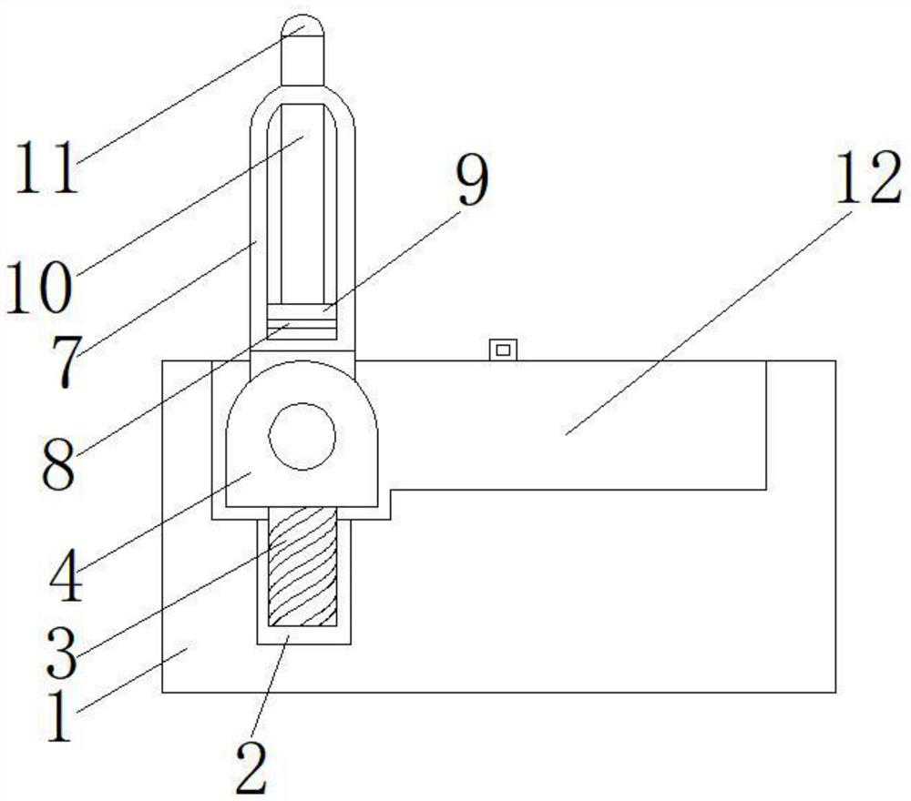
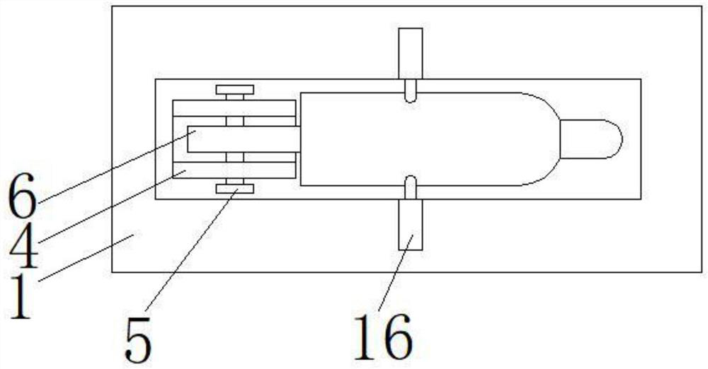
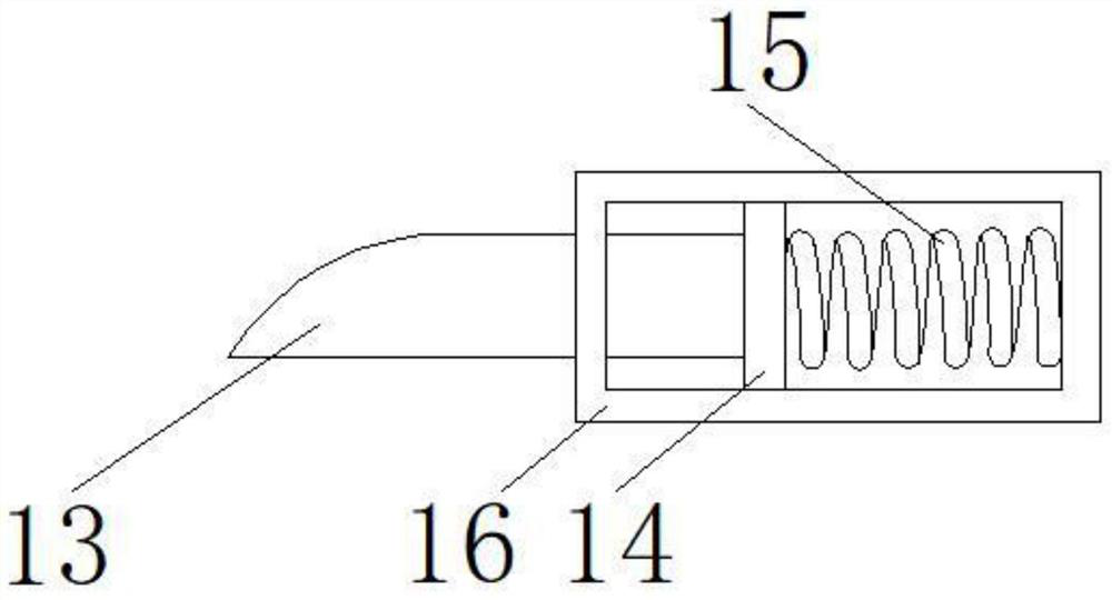
[0023] see Figure 1-4 , the present invention provides a technical solution: an antenna structure of an electronic device, including an electronic device main body 1, a connecting block 6 and a receiving groove 12, a threaded groove 2 is provided inside the electronic device main body 1, and the inside of the threaded groove 2 is installed There is a threaded block 3, threaded connection between the threaded groove 2 and the threaded block 3, and bonding betw...


PUM


Abstract

The invention discloses an antenna structure of electronic equipment, which comprises an electronic equipment main body, a connecting block and an accommodating groove, a threaded groove is formed in the electronic equipment main body, a fixed block is fixed above the threaded block, the connecting block is located above a positioning pin, a rubber block is arranged in a sleeve rod, a supporting rod is arranged above the sliding block, the accommodating groove is located above the electronic equipment body, a check block is arranged above the accommodating groove, a limiting block is fixed behind the check block, a spring is arranged behind the limiting block, and a fixing rod is arranged outside the spring. Compared with an existing common antenna structure, the antenna structure for the electronic equipment can be accommodated in the accommodating groove, so that the space can be saved, the antenna structure can be prevented from being damaged, and meanwhile, the antenna structure is provided with an adjusting structure, so that the height and the angle of the antenna structure can be adjusted, and the signal receiving strength of the equipment can be improved.

Description

technical field [0001] The invention relates to the technical field of antenna structures, in particular to an antenna structure of an electronic device. Background technique [0002] An antenna is a transformer that converts the guided wave propagating on the transmission line into an electromagnetic wave propagating in an unbounded medium (usually free space), or vice versa, used in radio equipment to transmit or receive electromagnetic waves part. [0003] The current antenna structure will increase the space occupied by the device, which makes the device inconvenient to carry. At the same time, the current antenna is exposed outside the device and is easy to break, resulting in economic losses. Therefore, the current antenna structure is not very good. Satisfy people's use needs, aiming at the above situation, carry out technological innovation on the basis of the existing antenna structure. Contents of the invention [0004] The purpose of the present invention is t...

Claims


Application Information

Patent Timeline
Patent Type & Authority Applications(China)
IPC IPC(8): H01Q1/08H01Q1/10H01Q1/12H01Q1/22H01Q3/08
CPCH01Q1/084H01Q1/10H01Q1/1235H01Q1/22H01Q3/08
Inventor 梁兴辉
Owner XIAN RENKE ELECTRONICS TECH CO LTD
Why Eureka
Try Eureka