
High-frequency connector crimping device

A high-frequency connector and crimping device technology, applied in the direction of connection, circuit/collector parts, electrical components, etc., can solve the problems of plastic deformation of the protective plate, affecting assembly and quality, deformation, etc., and achieve uniform force. Effect

Pending Publication Date: 2021-05-11
大连长丰实业总公司
View PDF0 Cites 0 Cited by
  • Summary
  • Abstract
  • Description
  • Claims
  • Application Information

AI Technical Summary

Problems solved by technology

[0003] In the process of embedding the circular protective plate of the high-frequency connector into the shell of the high-frequency connector, the high-frequency connector is generally placed on a table or a support plane, and the protective plate is directly smashed with a hammer or other heavy object. In the process of being inserted into the shell of the high-frequency connector, the protection plate is easily deformed due to uneven force during the process, and the assembly with the shell of the high-frequency connector is uneven, and one side is convex and the other is concave. It will also damage the high-frequency connector shell, deform it, and affect assembly and quality

Method used


Image

  • High-frequency connector crimping device
  • High-frequency connector crimping device
  • High-frequency connector crimping device

Examples


Embodiment Construction

[0028] In order to enable those skilled in the art to better understand the solutions of the present application, the technical solutions in the embodiments of the present application will be clearly and completely described below in conjunction with the drawings in the embodiments of the present application.

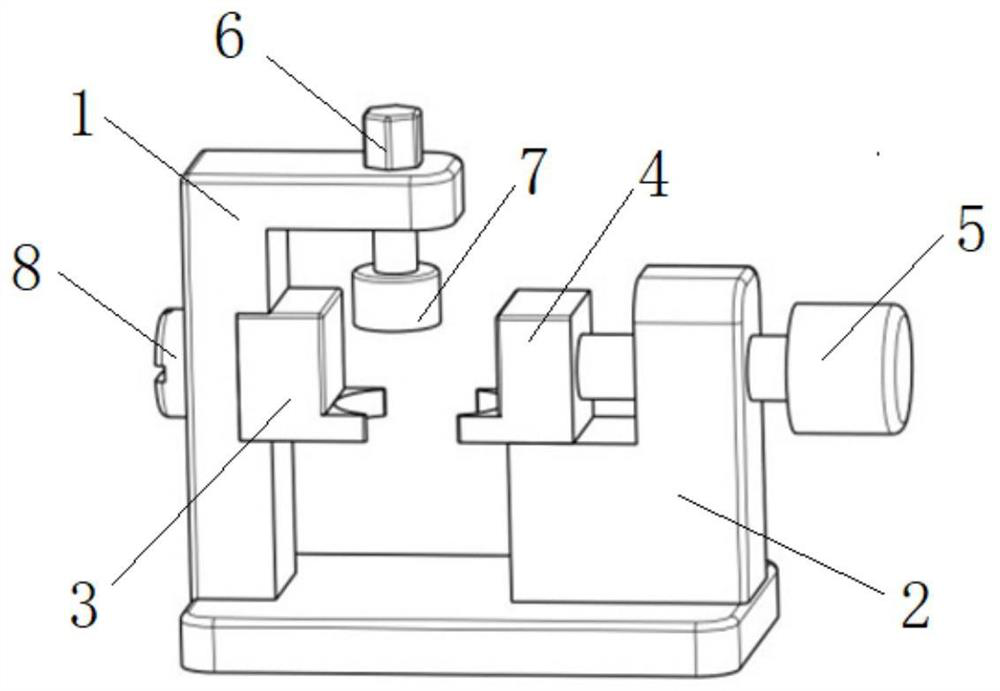
[0029] Such as figure 1 As shown, a high-frequency connector crimping device includes a base 1 , a support 2 , a fixed splint 3 , a movable splint 4 , an adjusting bolt 5 , a feed bolt 6 , a pressing plate 7 and a fixing bolt 8 .

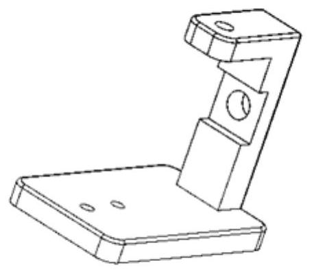
[0030] The base 1 is a C-shaped frame integrally processed by the upper plate, the lower plate and the vertical plate between the upper plate and the lower plate; wherein, the fixed splint 3 is installed on the vertical plate through the fixing bolt 8, and is located at C Inside the C-shaped frame; the feed bolt 6 is installed in the threaded hole of the upper plate, and the end where the feed bolt 6 penetrates into the C-shaped frame is also...


PUM


Abstract

The invention provides a high-frequency connector crimping device. The high-frequency connector crimping device comprises a base, a support, a fixed clamping plate, a movable clamping plate, an adjusting bolt, a feeding bolt, a pressing plate and a fixing bolt. The distance between the movable clamping plate and the fixed clamping plate is adjusted through the adjusting bolt, clamping of the high-frequency connector is achieved, the distance between the pressing plate and the two clamping plates is adjusted through the feeding bolt, and pressing connection of a protection plate of the high-frequency connector is achieved. In other words, compared with the situation that the high-frequency connector protection plate and the shell are very prone to deformation due to uneven stress in the original machining process, the pressing connection part can be accurately positioned, then the protection plate and the shell of the high-frequency connector are rapidly pressed and assembled, it is ensured that the protection plate does not deform in the pressing connection process, and is embedded into the shell under uniform stress, the shell of the high-frequency connector is not damaged, and the device plays a role in protecting welding spots of the high-frequency connector.

Description

technical field [0001] The invention belongs to the technical field of aviation equipment, and in particular relates to a high-frequency connector crimping device. Background technique [0002] JTNC-JW5 high-frequency connectors are usually used for connecting components on aircraft cables or installing electronic equipment. It and another auxiliary mating connector mainly perform repeated electrical connections and separations between two or more circuits. , which plays the role of transmitting signals. The connection between the high-frequency connector and the core wire of the high-frequency feeder adopts a welding process. After welding, its circular protective plate needs to be embedded in the shell of the high-frequency connector along the outer circumference to protect the welding. [0003] In the process of embedding the circular protective plate of the high-frequency connector into the shell of the high-frequency connector, the high-frequency connector is generally...

Claims


Application Information

Patent Timeline
IPC IPC(8): H01R43/048
CPCH01R43/048
Inventor 施娟王超李凤梧孙善轲李航
Owner 大连长丰实业总公司
Learn More