A cable transposition erection structure in a subdivided cable tunnel

A cable tunnel and subdivision technology, which is applied in the direction of cable installation, cable installation, and electrical components in the tunnel, can solve the problems of inconvenient use and operation and maintenance of cable tunnels, low reliability, and reduced floor space, etc., to achieve Multi-angle assembly connection, safe switching connection mode, and the effect of ensuring circuit safety

Active Publication Date: 2022-05-03
国核电力规划设计研究院重庆有限公司
View PDF0 Cites 0 Cited by
  • Summary
  • Abstract
  • Description
  • Claims
  • Application Information

AI Technical Summary

Problems solved by technology

[0003] When the transmission line is laid by cables, the main workload and investment are the construction of civil channels. Therefore, under the premise of determining the cable laying method, reducing the section size and reducing the occupied area can effectively save engineering investment. In order to improve the reliability of power supply, power cables can be used Different passages or subdivided tunnels are used for laying. Because subdivided cable tunnels can share part of the wall, reducing the width of the land, and at the same time, the relevant procedures can be completed at one time, and the external coordination workload is relatively small. In urban cable passages, subdivided There will be more and more cabin tunnel applications. At present, there are many problems in the design of sub-compartment cable tunnels, which is not convenient for the use, operation and maintenance of cable tunnels;
[0004] For the problem of cable laying and transposition, due to the large diameter of the cable, the transposition of the through-wall casing is not conducive to the laying of the cable. Because the cables cross at the transposition and the opening is a weak link, the cables cannot be isolated, posing safety hazards and low reliability. At the same time, if the cables pass through the pedestrian aisle during transposition, it will affect the passage of personnel

Method used


Image

  • A cable transposition erection structure in a subdivided cable tunnel
  • A cable transposition erection structure in a subdivided cable tunnel
  • A cable transposition erection structure in a subdivided cable tunnel

Examples


Embodiment approach

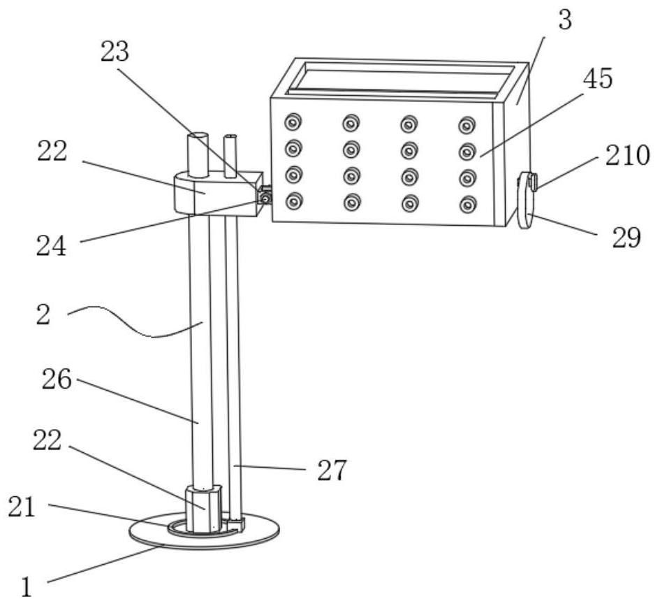
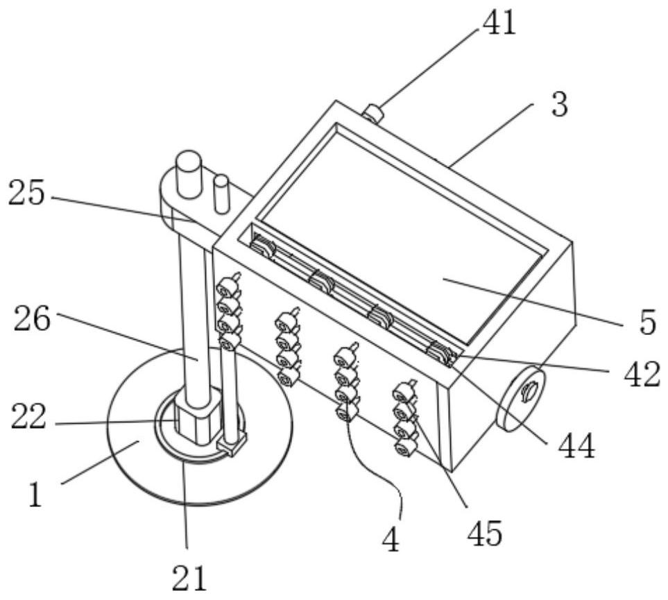
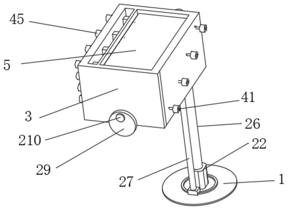
[0029] As an embodiment of the present invention, the connection structure 4 includes a first connection terminal 41, a sliding pad 42, a pressing spring 43, a conductive pad 44 and a second connection terminal 45, and the inside of the exchange box 3 is set There is a limiting plate, a sliding hole is provided in the limiting plate, a conductive rod is arranged on one side of the sliding plectrum 42, and the conductive rod runs through the sliding hole, and an extruding spring 43 is fixedly connected to the sliding plectrum 42. The extruding spring 43 is fixedly connected with a conductive plectrum 44, a plurality of first connection terminals 41 are embedded in one side of the exchange box 3, and a plurality of first connecting terminals 41 are embedded in the other side of the exchange box 3. There are a plurality of second connection terminals 45, the inside of the exchange box 3 is provided with a multi-layer isolation layer 5, the first connection terminal 41 and the slid...


PUM


Abstract

The invention discloses a cable transposition erection structure in a subdivided cable tunnel, which comprises a bottom plate, a vertical plate, a horizontal plate, a transition structure, a sliding structure, a chute, a layered position-limiting structure, and a stretching wire-receiving structure. The two ends of the top side of the vertical board are respectively vertically installed with vertical boards, the tops of the two vertical boards are welded with horizontal boards, the bottom side of the horizontal boards is provided with transitional structures, and one side of the vertical boards is provided with a chute. One side of the vertical plate is equipped with a sliding structure, and the upper and lower sides of the sliding structure are respectively equipped with a layered limit structure and a stretching wire take-up structure. Through the layered limit structure, various wire harnesses are placed in the separation Then, with the cooperation of the second positioning pin, the closing plate is fixed on the side of the layered seat, and the rubber pad is used to squeeze and fix the cable, which can realize the arrangement and fixing of the cables. With the cooperation, it is possible to sort out, classify and fix various cables to ensure clear lines and reduce the occurrence of danger.

Description

technical field [0001] The invention relates to the technical field of grid erection, in particular to a cable transposition erection structure in a subdivided cable tunnel. Background technique [0002] With the acceleration of urbanization and the continuous improvement of people's requirements for quality of life, there are more and more restrictions on the use of overhead transmission lines, and more cables will be used for new transmission channels; There will be a large number of overhead transmission lines for underground transformation, and new cable channels for laying; [0003] When the transmission line is laid by cables, the main workload and investment are the construction of civil channels. Therefore, under the premise of determining the cable laying method, reducing the section size and reducing the occupied area can effectively save engineering investment. In order to improve the reliability of power supply, power cables can be used Different passages or sub...

Claims


Application Information

Patent Timeline
Patent Type & Authority Patents(China)
IPC IPC(8): H02G9/00H02G9/08
CPCH02G9/00H02G9/08
Inventor 李东津向城名刘韬张华宇艾羽飞高新杰
Owner 国核电力规划设计研究院重庆有限公司
Why Eureka
Try Eureka