Automobile part forming equipment

A technology for auto parts and forming equipment, applied in forming tools, metal processing equipment, feeding devices, etc., can solve problems such as low efficiency and difficult control

Inactive Publication Date: 2021-05-14
顾元帅
View PDF0 Cites 0 Cited by
  • Summary
  • Abstract
  • Description
  • Claims
  • Application Information

AI Technical Summary

Problems solved by technology

[0003] The purpose of the present invention is to solve the shortcomings of low efficiency

Method used


Image

  • Automobile part forming equipment
  • Automobile part forming equipment
  • Automobile part forming equipment

Examples


Embodiment Construction

[0021] The following description serves to disclose the invention to enable those skilled in the art to practice the invention. The preferred embodiments described below are given by way of example only, and other obvious modifications will occur to those skilled in the art.

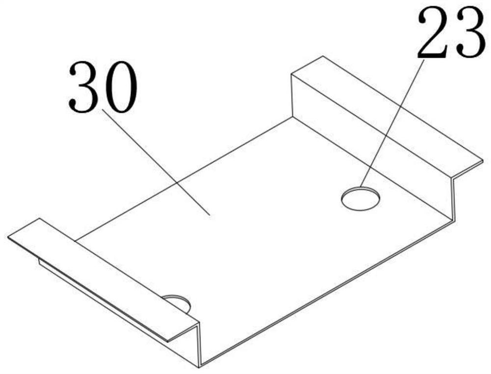
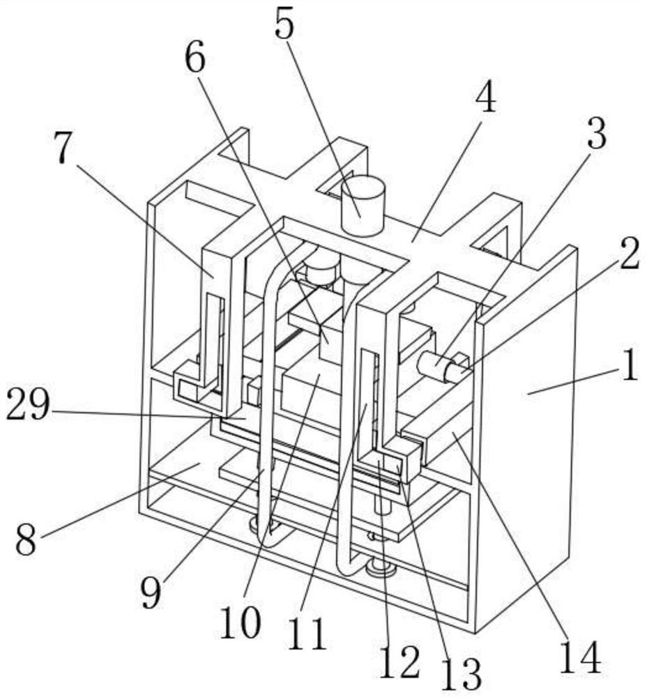
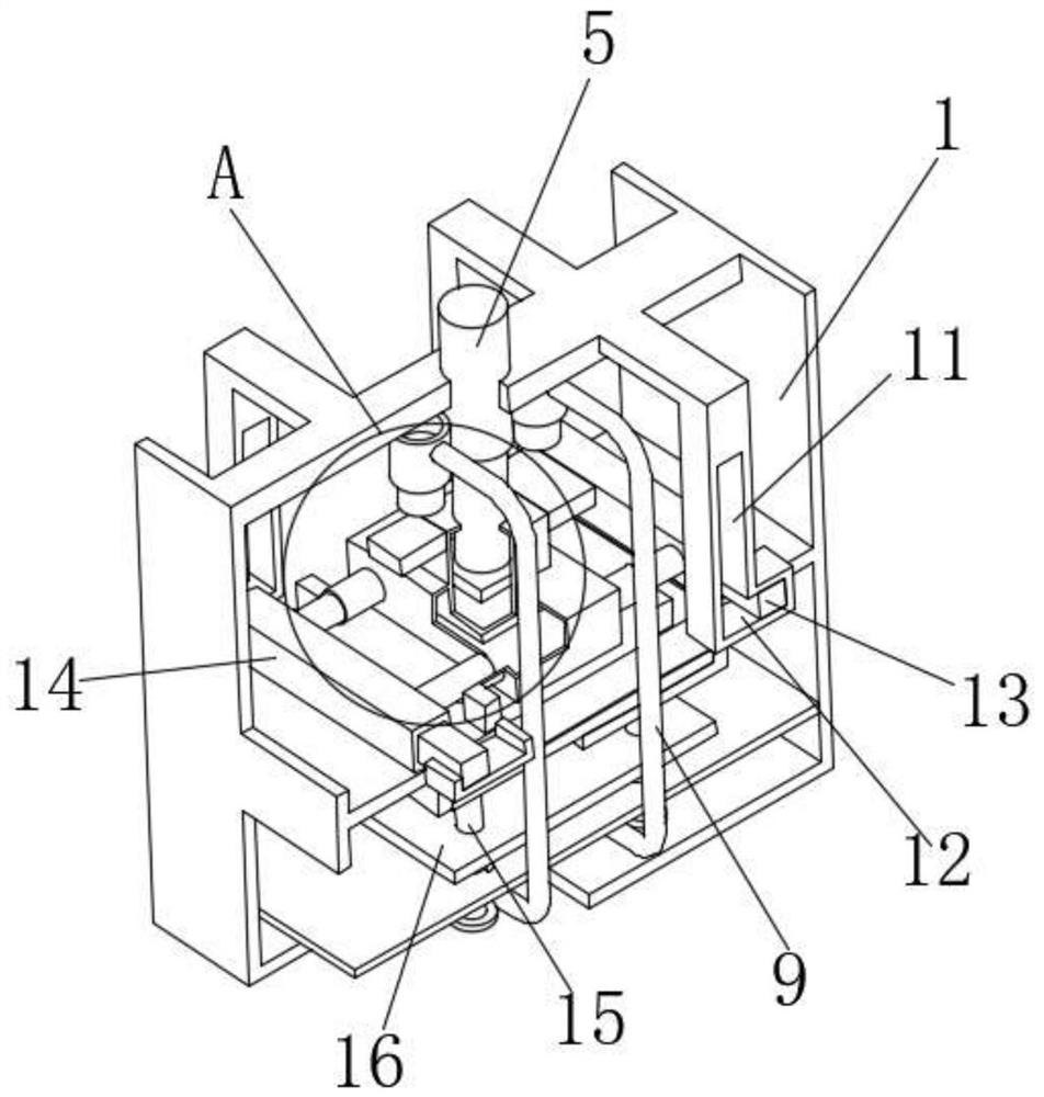
[0022] like Figure 1-Figure 7 The shown a kind of auto parts molding equipment comprises U-shaped installation frame 1, and the middle part of installation frame 1 is fixedly installed with U-shaped forming groove 24, and the forming groove 24 is provided with the bending mold 29 that matches with its shape, The top of the bending die 29 is fixed with an empty box 10, and the top of the empty box 10 is fixed with a connection box 6. The bottom of the connection box 6 communicates with the empty box 10, and the empty box 10 and the connection box 6 are filled with hydraulic oil. A piston plate 20 matching its cross-sectional shape is slidably installed, and the top surface of the piston plate 20 is fixe...


PUM


Abstract

The invention relates to the technical field of forming equipment, in particular to automobile part forming equipment. The automobile part forming equipment comprises a U-shaped mounting frame, wherein a U-shaped forming groove is fixedly formed in the middle of the mounting frame; a bending mold matched with the forming groove in shape is arranged in the forming groove, and an empty box is fixed to the top of the bending mold; a connecting box is fixed to the top of the empty box, the bottom of the connecting box communicates with the empty box, and the empty box and the connecting box are filled with hydraulic oil; a piston plate matched with the empty box in section shape is slidably arranged in the empty box, and the top face of the piston plate is fixedly connected with a vertically-arranged hydraulic cylinder; the hydraulic cylinder is fixedly connected with the middle of a top plate, and the top plate is fixedly connected with the top of the mounting frame; the two sides of the empty box are each fixedly connected with two first sleeves; and one end of each first sleeve communicates with the interior of the empty box. One-time forming of automobile parts can be conveniently achieved, efficiency is improved, and errors are reduced.

Description

technical field [0001] The invention relates to the field of molding equipment, in particular to an auto parts molding equipment. Background technique [0002] Auto parts often need to be bent and formed in the process of processing, such as attached figure 1 The automobile part of the shape shown is formed by bending a flat plate. The process of bending and forming it in the prior art is as follows: first, two creases are folded inwardly at 90°, and then two creases are folded. A crease that is bent 90° to the outside requires a total of four bends to realize the shape, which requires manual control, which is not only inconvenient to operate, but also prone to folding errors, which increases the cost. Contents of the invention [0003] The object of the present invention is to solve the disadvantages of low efficiency and difficult control in the prior art, and propose a molding equipment for auto parts. [0004] In order to achieve the above purpose, the technical solu...

Claims


Application Information

Patent Timeline
IPC IPC(8): B21D11/20B21D11/22B21D43/00B21D37/10
CPCB21D11/20B21D11/22B21D37/10B21D43/003
Inventor 顾元帅
Owner 顾元帅
Why Eureka
Try Eureka