Brazing method for cable shielding layer and shell

A cable shielding layer and brazing method technology, applied in welding equipment, metal processing equipment, manufacturing tools and other directions, can solve the problems of low production efficiency, low production efficiency, difficult brazing method, etc., to achieve uniform and stable shape, The cost of welding is low and the effect of ensuring the quality of brazing

Inactive Publication Date: 2012-02-15
HARBIN INST OF TECH SHENZHEN GRADUATE SCHOOL
View PDF5 Cites 8 Cited by
  • Summary
  • Abstract
  • Description
  • Claims
  • Application Information

AI Technical Summary

Problems solved by technology

However, since the insulating surface of the cable, the insulating layer covered by the cable core wire, and the cable core wire and electronic components are often pre-formed brazing joints before the shielding layer is welded, the brazing method of overall heating is difficult to carry out.
There are also certain problems in the local brazing method. For example, although laser brazing can achieve accurate local heating, the laser equipment is relatively expensive, and the brazing joint between the shielding layer and the shell is in the shape of a ring, which leads to the formation of the laser brazing joint. The uniformity and consistency are poor, and more importantly, when there are multiple cables connected to the shell, laser brazing can only be heated point by point, and the production efficiency is not high; resistance brazing must use Cu electrodes to directly Contacting the shell and the shielding layer and applying a certain pressure is not good for the forming of the ring-shaped joint, and the high current required for brazing is likely to cause the electronic components in the shell to fail due to electrical shock, and there is also a problem of low production efficiency ; Manual soldering iron brazing is currently the most widely used method, but the heat input of soldering iron brazing cannot be accurately controlled, the shape of solder joints is not good and the consistency is poor, the production efficiency is low, and the welding quality is greatly affected by the skills of workers
[0005] Although the existing electromagnetic induction brazing can realize non-contact heating, the existing method can only braze a single joint, and the heating coil is in a closed spiral ring structure, and it is impossible to place the long cable and the housing in the heating In the middle of the coil, causing problems such as low efficiency and difficult process

Method used


Image

  • Brazing method for cable shielding layer and shell
  • Brazing method for cable shielding layer and shell
  • Brazing method for cable shielding layer and shell

Examples


Embodiment Construction

[0031] The following are examples of the present invention, through which the present invention can be further clearly understood in conjunction with the accompanying drawings, but they are not limitations of the present invention.

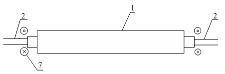
[0032] figure 1 It is a schematic diagram of the electromagnetic induction brazing principle for shell-cable. In the figure, the cable 2 passes through the branching hole at both ends of the housing 1, and the electromagnetic induction heating coil 7 is placed at the position where the cable shielding layer and the branching hole are to be welded.

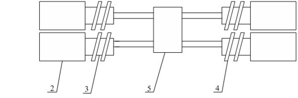
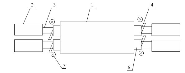
[0033] Such as figure 2 As shown, a tinned aluminum shell 1 with a length of 45 mm and a four-core cable 2 with a diameter of 5 mm are selected. Brazing. The solder wire 4 used is a Sn-3Ag-0.5Cu solder wire with a diameter of 2mm, and the melting point of the solder wire is 217°C. By means of preset, the Sn-3Ag-0.5Cu solder wire 4 is wound on the part of the cable shielding layer 3 to be brazed, a...


PUM

PropertyMeasurementUnit
diameteraaaaaaaaaa

Abstract

The invention discloses a brazing method for a cable shielding layer and a shell, wherein wire branching holes are formed in two ends of the shell; a cable passes through the wire branching holes; and the brazing method comprises the following steps of: winding, namely winding brazing wires on parts, opposite to the wire branching holes, of the cable shielding layer; fixing, namely fixing the cable, the shell and the brazing wires by a clamp; heating, namely, putting a brazing part into an induction coil and heating the brazing part by induction heating equipment; and cooling, namely stopping heating until the brazing part is cooled. By the brazing method, one-time molding of joints at two ends of the shell can be realized, the shape of the shell is uniform and stable, the brazing quality is easy to guarantee, and efficient and automatic production requirements can be met.

Description

technical field [0001] The invention relates to a brazing method for a cable shielding layer and a shell, which is especially suitable for performing non-contact rapid local heating only on the parts to be brazed at both ends of the shell, so as to realize efficient and reliable brazing between the shielding layer and the cable shielding layer at one time. . Background technique [0002] Cables are widely used to transmit signals in electrical and electronic components, sensors, and microwave devices of communication and medical equipment. In order to ensure that the electronic equipment system is free from radio frequency and electromagnetic interference, it is necessary not only to electromagnetically shield the shell of the electronic equipment, but also to shield the connection of each equipment. cable. In order to protect the line signal from electromagnetic interference, heat-shrinkable insulating rubber is usually used outside the wires of the cable, and then a shiel...

Claims


Application Information

Patent Timeline
Patent Type & Authority Applications(China)
IPC IPC(8): B23K1/002
Inventor 计红军李明雨王强肖勇
Owner HARBIN INST OF TECH SHENZHEN GRADUATE SCHOOL
Why Eureka
Try Eureka